YS100_Ope_E.pdf - 第76页
2-9 2 asic operation Code Error name and description Ea29922 FEEDER CART(REAR1) IS NOT SET State Emergency stop function is activated. Cause Feeder cart (rear 1) is not set. Action Set the Feeder Cart or close the Cart…
2-8
2
asic operation
n
Others
Code Error name and description
Ea00109
EMERGENCY STOP FUNCTION DURING MOUNT
State
EMERGENCY STOP FUNCTION is executed duringmounting sequense. So, there is danger that
mountsequense finished under the unusual condition. Can it stop automatically after it installs it when an
automatic driving is restarted, and the image at the installation position be confirmed.
Cause Emergency stop was triggered during component placement.
Action Use "trace" to check whether the component is placed at the specified point.
Ea00818
QUICK STOP ACTIVE
State QUICK STOP FUNCTION is now active.
Cause Emergency stop was triggered by the "conveyor width safety check sensor".
Action Check the status of the conveyor width safety check sensor.
Ea02722
DON'T YOU NEED HALFWAY CONTINUE?
State
A board that is not finished to mount exist on the mounting position. If you continue auto running, a halfway
board may be transferred. Please confirm the board condition and execute halfway continue command if
necessary.
Cause
A board for which component mounting is not completed is left in the component placement position. If
automatic operation continues as is, then the unfinished board may be transferred downstream.
Action
Check the board in the component placement position. When it is not finished, run "Halfway Continue"
command to resume component mounting on that board.
Ea02889
EMERGENCY STOP FUNCTION DURING PICK
State
EMERGENCY STOP FUNCTION is executed during picking sequence. There is a chance that the picking
sequence finished under suspicious conditions. Please check condition of the component.
Cause
Emergency stop was triggered during component pickup. Component pickup operation might have been
unstable.
Action Check how the component is being picked up.
Ea07871
CAN NOT EXECUTE COMMAND
State
Can not execute this command , because RESET is not finished completely. Please try the RESET command
again, and finish it.
Cause Unable to run commands since reset is not complete.
Action Perform a reset again.
Ea01277
X1 Axis 2nd LIMIT OVER
State Move the axis until error message disappears. The "EMERGENCY STOP" light will go off.
Cause X1-axis secondary limit was exceeded.
Action Move the X1 axis by hand to a safe position.
Ea01278
Y1 Axis 2nd LIMIT OVER
State Move the axis until error message disappears. The "EMERGENCY STOP" light will go off.
Cause Y1-axis secondary limit was exceeded.
Action Move the Y1 axis by hand to a safe position.
Ea29920
FEEDER CART(FRONT1) IS NOT SET
State Emergency stop function is activated.
Cause Feeder cart (front 1) is not set.
Action
Set the Feeder Cart or close the Cart Cover, and press the READY button to re-enable the machine.
The "EMERGENCY STOP" light will go off.
Ea29921
FEEDER CART(FRONT2) IS NOT SET
State Emergency stop function is activated.
Cause Feeder cart (front 2) is not set.
Action
Set the Feeder Cart or close the Cart Cover, and press the READY button to re-enable the machine.
The "EMERGENCY STOP" light will go off.

2-9
2
asic operation
Code Error name and description
Ea29922
FEEDER CART(REAR1) IS NOT SET
State Emergency stop function is activated.
Cause Feeder cart (rear 1) is not set.
Action
Set the Feeder Cart or close the Cart Cover, and press the READY button to re-enable the machine.
The "EMERGENCY STOP" light will go off.
Ea29923
FEEDER CART(REAR2) IS NOT SET
State Emergency stop function is activated.
Cause Feeder cart (rear 2) is not set.
Action
Set the Feeder Cart or close the Cart Cover, and press the READY button to re-enable the machine.
The "EMERGENCY STOP" light will go off.
2-10
2
asic operation
2. Operation screen and buttons
The basic configuration and operation methods of the software screens are explained in this section. Please
read through this section before operating the machine.
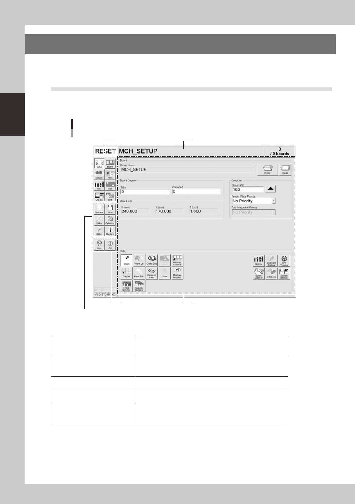
2.1 Basic configuration of operation screen
The operation screen can be divided into the "Status area", "Main menu button area" and "Submenu button and
parameter area" as shown below.
Main menu button area 1
Main menu button area 2
Main menu button area 3
Status area
Operation screen basic configuration
Setup screen
Submenu button and parameter area
24200-L1-00
n
Area on screen
Status area
Displays the current machine status on the left end, the selected board
name in the middle, and the number of boards that have been produced
on the right end.
Main menu button area 1
Shows the main menu buttons used to operate the machine. The
submenu button and parameter area will change according to the
selected main menu button.
Main menu button area 2
Shows the menu buttons used to call up auxiliary functions of the
machine.
Main menu button area 3
Shows the [Help] button to call up the help screen and also the [Off]
button to quit the software.
Submenu button and parameter area
Displays the submenu buttons and parameters for machine operation
and data setting. This area will change according to the selected main
menu button.