00191471-01.pdf - 第21页
Servicing Instructions HS-50 Replacing the Y-Ax is Sca le 01/99 Issue 21 3 Fig. 3 - 1 Removing the incremental encoder for the y axis K e yt oF i g . 3-1 (1) Main gan try (2) 2 x M3 x 10 hex agon soc ket-head s crews (3)…

Replacing the Y-Axis Scale Servicing Instructions HS-50
01/99 Issue
20
3 Replacing the y axis scale
3.1 Tools and equipment
– Pasting device for the y axis scale S50, kit, item no. 00344862-01 incl.
Firmer chisel, approximately 20 mm wide, item no. 00345526-01 3
Multiflex pad A-VFN, red, item no. 00345527-01 3
Protective gloves, item no. 00091001-01 3
Reinforced cloths, Kimnet 6036, item no. 00331395-01 3
Pasting device for the y axis scale, item no. 00344861-01 3
Two guides 3
– Set of DIN 911 Allen keys
– Diagonal cutter
– Ethyl alcohol
– Cable ties
– Feeler gauge
– SITEST program
3.2 Parts
Scale, y axis, for HS-50, from item number 00335966-02 3
3.3 Removing the y axis scale
DANGER POWERFUL MAGNETIC FIELD
Always follow the special safety instructions when working in the vicinity of powerful magnetic
fields (see section 2, page 18 onward). 3
à Remove the incremental encoder for the y axis (item 3 in Fig. 3 - 1) on the two main gantries
(1 and 4 or 2 and 3).
Servicing Instructions HS-50 Replacing theY-Axis Scale
01/99 Issue
21
3
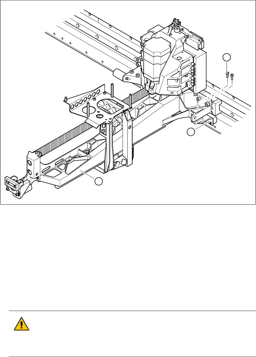
Fig. 3 - 1 Removing the incremental encoder for the y axis
KeytoFig.3-1
(1) Main gantry
(2) 2 x M3 x 10 hexagon socket-head screws
(3) Incremental encoder, y axis
3
à Loosen the two M3 x 10 hexagon socket-head screws (item 2 in Fig. 3 - 1).
à Attach the incremental encoder to the main gantry using cable ties.
CAUTION 3
When you remove the incremental encoder, make sure that you do not damage its scanning
surface. 3
à Push the two main gantries to the left.
3
1
2
Replacing the Y-Axis Scale Servicing Instructions HS-50
01/99 Issue
22
à Put on a pair of protective gloves.
à Starting from the right-hand side of the placement system, use the firmer chisel (item 2 in Fig.
3 - 2) to detach the y axis scale (item 1 in Fig. 3 - 2) from the contact surface. Work along the
scale until you reach the two main gantries on the left-hand side.
3
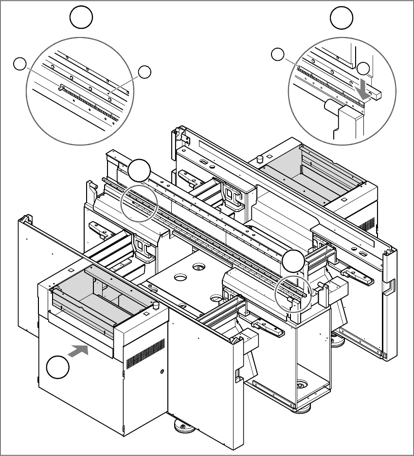
Fig. 3 - 2 Removing the y axis scale
(1) Scale for the y axis (2) Starting point for firmer chisel
(3) Sleeve (4) Guide rail of y axis recirculating ball screw unit
T PCB transport direction 33
T
B
A
B
3
4
A
1
2