SIPLACE Line Computer UNIX.pdf - 第154页
4 Data Management Us er Manual Line Computer UNIX 4.5 File Display Use r Interface Software Version 5 02.xx 10 /2000 Issue 152 I t I I 4.5.2.3 OPTIO NS menu - Data T ype This me nu option enables a filter to be selecte d…

User Manual Line Computer UNIX 4 Data Management
Software Version 502.xx 10/2000 Issue 4.5 File Display User Interface
151
I
t I I
Apart from "Find/replace", the following menu items are also contained in the "SERVICES" menu by means of
which the respective editors may be started. With the exception of the "Feeder Editor" menu item, the other
items are only active if a particular character string is hightlighted in the display area.
- Component Editor
- Package Form Editor
- PCB Editor
- Setup Modification Generator
- Adhesive Pattern Editor
- Feeder Editor
Example: Starting the PCB Editor
● In the display area highlight a character string with the cursor and then select SERVICES --> PCB
Editor. The PCB Editor opens. The highlighted character string is entered in the editor as the
name of the PCB.
NOTE
If the name of an already existing PCB is highlighted (with or without suffix), the data of the selected
PCB are displayed in the PCB Editor; in all other cases a new PCB is created whose name corre-
sponds to the name of the highlighted character string. The suffix ".la" is added automatically.
NOTE
The procedure described above also applies to the Component Editor, Package Form Editor and Setup
Modification Generator. To start the Setup Modification Generator, the complete character string needs to
be highlighted for the path in which the setup file (e.g. Anlagen/Linie.ak/Teil.va/rüstung1.ar) is located.
4 Data Management User Manual Line Computer UNIX
4.5 File Display User Interface Software Version 502.xx 10/2000 Issue
152
I
t I I
4.5.2.3 OPTIONS menu
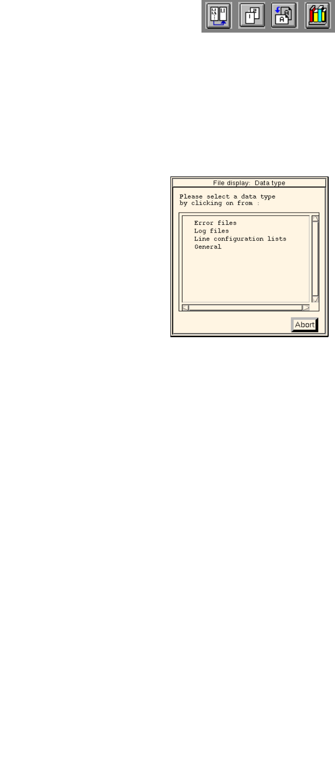
- Data Type
This menu option enables a filter to be selected from a number of predefined filters which will then
appear in the FSB as the default setting upon selecting "FILE --> Open...".
● Select OPTIONS --> Data type.
The dialog box containing the listing of the predefined filters is opened.
● Click on desired data type, e.g. Error files (or Abort if the dialog box is to be closed without
selecting a filter).
The dialog box is closed.
- Printer Selection
This menu items enables an installed printer to be selected.
● Select OPTIONS --> Printer selection.
The window for the printer selection is opened.
● Select desired printer type and confirm the selection with OK.
- Saving State
This menu item enables the data type and printer selected under Options to be saved so that these
presettings will be available immediately when the File Display is restarted.
● Click on OPTIONS --> Save state.
The currently set options for the data type and the printer selection are saved as default
settings.

User Manual Line Computer UNIX 4 Data Management
Software Version 502.xx 10/2000 Issue 4.6 CAD Import
153
I
t I I
4.6 CAD Import
Externally created placement files (e.g. files created on CAD systems, PPS systems, in databases, etc.) can
be easily adapted to the SIPLACE format with the aid of the user interface of the „CAD Import“ program.
The "CAD Import" program makes a distinction between two modes:
- Conversion mode (default mode)
Filters are used as the basis for the data import in the Conversion mode.
- Filter editing mode
The filters required for the determination of the required placement data from the files to be converted,
can be created or modified in the Filter editing mode.
When converting the placement data, a cluster size is calculated from the placement positions located at the
outermost positions. This cluster size can be changed to its actual size in a separate window of CAD Import.
In addition, the preset coordinate system can also be changed.
To display the PCB structure created from the converted and modified placement data, the graphics function
provided in the user interface of CAD Import is used.
4.6.1 Prerequisites/Preparatory Steps for the Import of Externally
Created Placement Files
- The placement file (CAD data file) must be available in the ASCII format.
- The name of the file must end with the suffix .cad.
- The file must be copied to the Master data/CAD-Bibliothek directory (see section 4.3.4.1).
- Each data line of a placement position must minimally contain the following PP data:
the component name,
the x and y-coordinates
the placement angle