SIPLACE Line Computer UNIX.pdf - 第156页
4 Data Management Us er Manual Line Computer UNIX 4.6 CAD Imp ort Software Version 502.xx 10/2000 Issue 154 I t I I 4.6.2 Starting CAD Import Dependin g on the operating mo de selec ted, the us er interfac e of CAD Impo …

User Manual Line Computer UNIX 4 Data Management
Software Version 502.xx 10/2000 Issue 4.6 CAD Import
153
I
t I I
4.6 CAD Import
Externally created placement files (e.g. files created on CAD systems, PPS systems, in databases, etc.) can
be easily adapted to the SIPLACE format with the aid of the user interface of the „CAD Import“ program.
The "CAD Import" program makes a distinction between two modes:
- Conversion mode (default mode)
Filters are used as the basis for the data import in the Conversion mode.
- Filter editing mode
The filters required for the determination of the required placement data from the files to be converted,
can be created or modified in the Filter editing mode.
When converting the placement data, a cluster size is calculated from the placement positions located at the
outermost positions. This cluster size can be changed to its actual size in a separate window of CAD Import.
In addition, the preset coordinate system can also be changed.
To display the PCB structure created from the converted and modified placement data, the graphics function
provided in the user interface of CAD Import is used.
4.6.1 Prerequisites/Preparatory Steps for the Import of Externally
Created Placement Files
- The placement file (CAD data file) must be available in the ASCII format.
- The name of the file must end with the suffix .cad.
- The file must be copied to the Master data/CAD-Bibliothek directory (see section 4.3.4.1).
- Each data line of a placement position must minimally contain the following PP data:
the component name,
the x and y-coordinates
the placement angle
4 Data Management User Manual Line Computer UNIX
4.6 CAD Import Software Version 502.xx 10/2000 Issue
154
I
t I I
4.6.2 Starting CAD Import
Depending on the operating mode selected, the user interface of CAD Import can be opened either by selecting
the CAD import option from the "PRODUCT" menu on the desktop, or by clicking on the CAD import icon in
the "Products" area.
Moreover, the user interface of CAD Import can also be opened via the Data Manager by clicking on a file with
the suffix .cad in the Master data/CAD-Bibliothek directory.
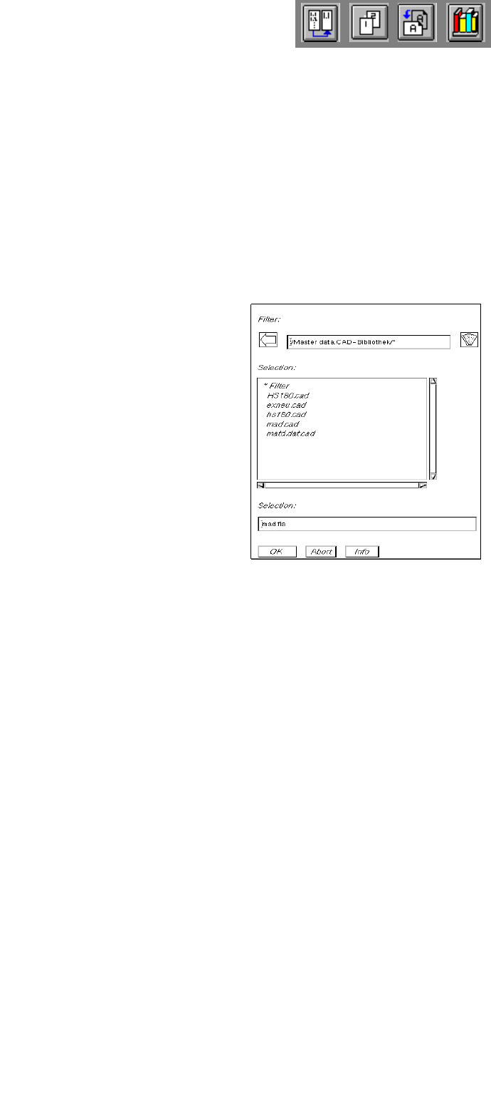
● Click on the CAD import icon on the desktop (or the "CAD import" menu item on the "PRODUCT"
menu). The FSB containing a listing of all available ".cad" files opens.
● Select the "xxx.cad" name of the desired file by double-clicking.
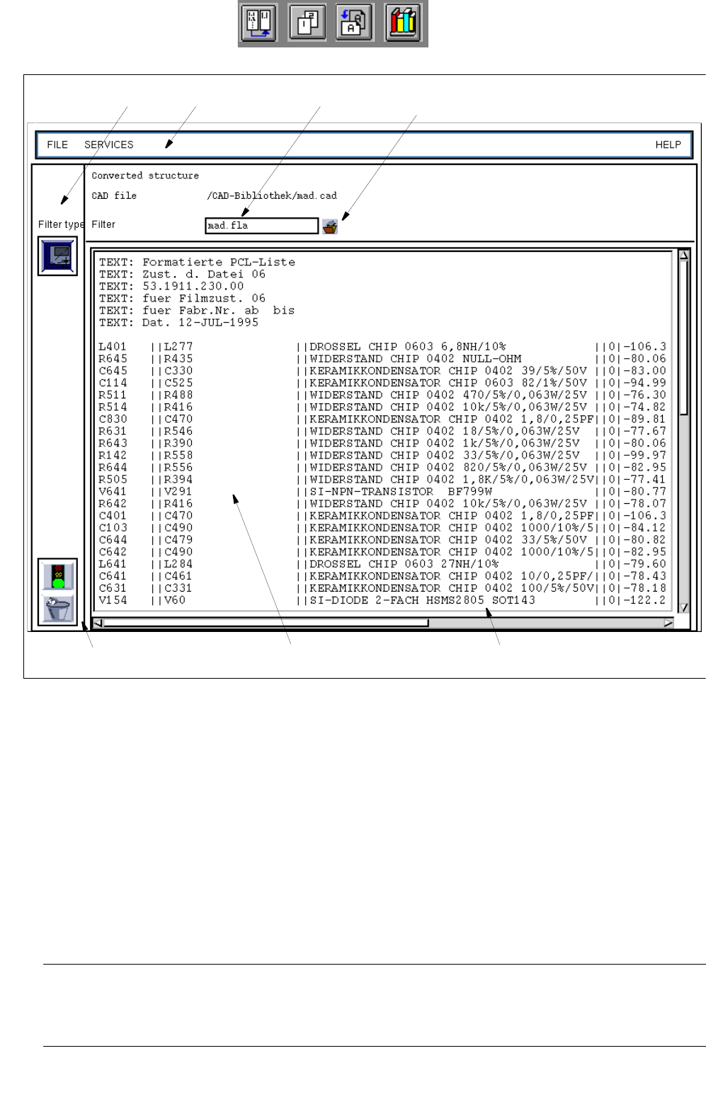
The main window of CAD Import (see
Fig. 4.6.1) opens.
The content of the selected file is displayed in the display area.
The name of the filter that was used most recently is entered above the display area,
adjacent to the filter selection button.
User Manual Line Computer UNIX 4 Data Management
Software Version 502.xx 10/2000 Issue 4.6 CAD Import
155
I
t I I
Fig. 4.6.1 "CAD Import" Window (Display of CAD Data)
The main window is subdivided as follows:
- Menu bar
- "Filter type" selection area (in this SW version without function)
- Filter selection button
- Display area
- Command area
Menu Bar
The menu bar contains the menus "FILE", "SERVICES" and "HELP".
Some menu items of the "FILE" menu are explained in
section 4.6.2.1.
The "SERVICES“ menu is described in section 4.6.2.2.
NOTE
Since the function and operation of the "HELP" menu are identical to those in other application programs
of the line computer, the menu is described in detail in chapt. 2.
Menu bar
Command area
CAD data
Filter selection
Display area
Selection area
"Filter type"
Filter name
button