SIPLACE Line Computer UNIX.pdf - 第170页
4 Data Management Us er Manual Line Computer UNIX 4.6 CAD Imp ort Software Version 502.xx 10/2000 Issue 168 I t I I
User Manual Line Computer UNIX 4 Data Management
Software Version 502.xx 10/2000 Issue 4.6 CAD Import
167
I
t I I
4.6.3.2 Editing a Filter
Allocation of the data from the CAD file to the position fields in the "PCB filter dialog" window is accomplished
by two successively performed single clicks. First the source (data field) is to be clicked on and then the
destination (position field). Other clicking sequences do not result in allocations.
For the allocation, a data field can be selected from any data line desired. All data fields that are then to be
allocated must be located on this selected data line, otherwise the data will not be accepted in the respective
position fields. Allocations can be deleted by clicking on the individual position fields with the right
mouse button.
Procedure:
● From the "PCB filter dialog" window select the "Field separator“ corresponding to the CAD data
(for details see
page 4 - 165).
● All other desired filter settings are to be performed in accordance with the structure of the CAD file
(for details see
page 4 - 164).
● In the "PCB type" editing field enter a name for the PCB type (for details see page 4 - 165).
● Select the processing type and the coordinate system (for details see page 4 - 166).
● Click on a data field (source) on any data line desired contained in the main window of CAD
Import. The data field is highlighted
.
● Click on the appropriate position field (destination) in the "PCB filter dialog" window.
The contents of the data field are transferred to the position field.
No plausibility check will be performed.
● All position fields are to be allocated the corresponding data fields in the same way.
NOTE
The data of an already-allocated data field are displayed underlined in the main window of CAD
Import.
● Click on OK for the filter data to be accepted.
The filter is saved under the current name, and the "PCB filter dialog" window closes.
User Manual Line Computer UNIX 5 Product / Component
Software Version 502.xx 10/2000 Issue 5.1 Component Editor
169
I
t I I
5 Product / Component
5.1 Component Editor
The Component Editor enables the user to completely describe the components in terms of their electrical
characteristics. In the Editor, the component type (e.g. diode), its electrical characteristics and its type of
processing (e.g. gluing, placing) are defined. Moreover, the component is assigned a package form no. in
accordance with its particular package design.
5.1.1 Starting the Component Editor
-
In the "programming mode" the Component Editor is activated by clicking on the Component icon on
the desktop or via the Data Manager (see
chapt. 4).
- If the LC program was installed for the "control mode", the Component Editor can be started via the
"PRODUCT" menu on the desktop, or via the Data Manager.
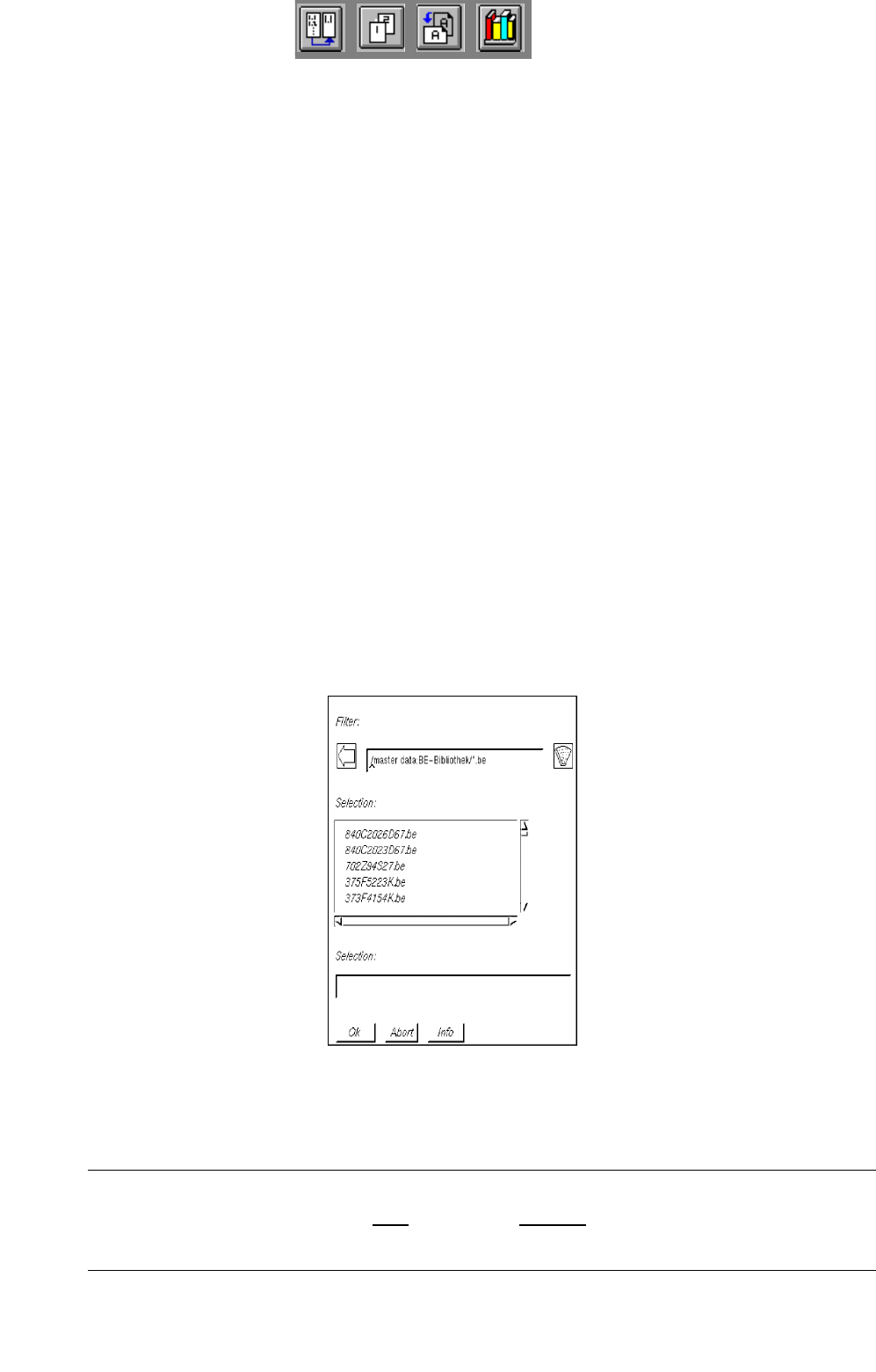
● Click on the Component icon on the desktop (or the "Component Editor" option on the
"PRODUCT" menu). The FSB containing the files of all previously defined components is opened.
● Select component "xx.be" by double-clicking, or enter new name on the keyboard and confirm
with OK.
The main window containing the Component Editor (see
Fig. 5.1.1) is opened.
NOTE
The component name may comprise max.
20 characters including the suffix ".be". Some characters
must not be used for the name, see chapt. 2, section 2.3 in this connection.