SIPLACE Line Computer UNIX.pdf - 第209页
User Manual Line Computer UNIX 6 Product / Package Form Software Vers ion 502.xx 10/2000 Issue 6.1 Pack age Form Editor 207 I t I I 6.1.2.10 Package Form Editor Selection Fields - "Handling data" Screen In the …
6 Product / Package Form User Manual Line Computer UNIX
6.1 Package Form Editor Software Version 502.xx 10/2000 Issue
206
I
t I I
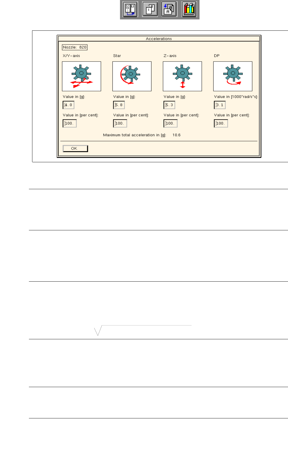
Fig. 6.1.11 Dialog Box for the Individual Setting of Acceleration Values for Each Axis
(applies only to nozzle types 4xx, 7xx, 8xx and 9xx)
NOTE
The acceleration value can either be entered in [g] for the x/y, star and z-axes, or in
[1000 x rad/s
2
] for the dp-axis. Or else, a value corresponding to a percentage of the maximum acce-
leration of the axis at issue can be entered.
● Click on the editing field of the desired axis.
● Enter the value and press the RETURN key or click into a different field.
From the value entered for the acceleration, the percentage value or, conversely, the value in [g] or
[1000 x rad/s
2
] is calculated immediately and automatically entered in the appropriate editing field.
NOTE
The acceleration values for the x/y, star and z-axes can be changed in increments of 0.1, and for the
dp-axis in increments of 100.
The maximum overall acceleration calculated from the acceleration values for the x/y and star axes is
displayed in [g] below the editing fields.
Max. overall acceleration = (accel. x + accel. star)
2
+ accel. y
2
● Confirm the entries by clicking on OK.
The dialog box closes.
The percentage value of the acceleration is displayed in the appropriate editing field in the view
area, provided the same value has been set for all axes.
NOTE
If the percentage value entered for the acceleration differs for one or more axes from the default
values (35%, 70% or 100%), the respective editing field only contains a broken line (----).

User Manual Line Computer UNIX 6 Product / Package Form
Software Version 502.xx 10/2000 Issue 6.1 Package Form Editor
207
I
t I I
6.1.2.10 Package Form Editor Selection Fields - "Handling data" Screen
In the selection fields a button is located next to each "handling type" (see Fig. 6.1.4).
The required "handling type" can be activated or deactivated by clicking on the corresponding button.
Selection field "Handling instructions"
This field serves to define the type of handling a component type will be subjected to during the placement
cycle.
- Vacuum test during pick-up When the component is picked up sensors are used to
check whether the component has been picked up.
- Vacuum test during placement Prior to being placed, the component is interrogated by means
of sensors to verify that the component is still attached to the
nozzle.
- Coplanarity check The coplanarity laser module determines by means of co-
planarity measurement whether pins of the component
are bent and whether it may have to be discarded.
- Aut. pick-up correction If this option is activated, the predetermined pick-up offset will be
automatically corrected at the station so that the component
will be picked up truly centered.
NOTE
For components for which a centered pick-up is not possible, the option "Aut. pick-up correction" must be
deactivated.

6 Product / Package Form User Manual Line Computer UNIX
6.1 Package Form Editor Software Version 502.xx 10/2000 Issue
208
I
t I I
Selection field "Centering"
This selection field serves to define the type of centering suited for the component type. For this purpose, the
setting "Centering in head" or "External centering" can be chosen from. Moreover, the centering procedure for
the particular centering type can be defined.
- Centering in head The component is centered by means of the revolver head or the
placement head on the HS-180 if any one of the following three
options is selected in addition.
with H jaws mech. centering by means of h-jaws (measuring jaws) of the
placement head of the HS-180.
with Z jaws mech. centering by means of z-jaws of the placement head of
the HS-180.
with camera optical centering by means of the component camera of the
revolver head.
- External Centering The component is centered externally by means of appropriate
centering devices of an HS-180, or by means of the IC camera
or flip-chip camera of a SIPLACE 80F3/F
4
optical The component is centered by means of the optical centering
station of an HS-180, or by means of the IC camera or flip-chip
camera of a SIPLACE 80F3/F
4
.
mechanical The component is centered using the mechanical centering
station. (function is not currently used)
Rotate before centering The component is turned into placement position prior to being
measured (centered) by means of the optical centering station of
an HS-180 or the IC camera of a SIPLACE 80F3/F
4
(by 90°, 180° or 270°)