SIPLACE Line Computer UNIX.pdf - 第213页
User Manual Line Computer UNIX 6 Product / Package Form Software Vers ion 502.xx 10/2000 Issue 6.1 Pack age Form Editor 211 I t I I 6.1.3 P ackage Form Definiti on 6.1.3.1 Definition of the Component ’ s Coordinate Syste…
6 Product / Package Form User Manual Line Computer UNIX
6.1 Package Form Editor Software Version 502.xx 10/2000 Issue
210
I
t I I
- Adhesive pattern In this field the number of the adhesive pattern is entered that has been
defined for the current package form (see chapt. 7).
- Dispense setting In this field a number from 1 to 10 is entered indicating the volume to be
dispensed. The number denotes the quantity of adhesive preset at the
adhesive metering unit for the corresponding adhesive volume setting.
The lowest setting (1) corresponds to the smallest adhesive quantity
dispensed.
NOTE
In the fields "Placing force" and "Dispense setting" numerals must be entered.
If no number is entered in the field "Adhesive pattern" a default value of "1" automatically applies to the
adhesive pattern, i.e. the adhesive dot is applied centrically with respect to the placement position.
- WPTC acceleration in y [g] Here, a value between > 0.1 and < 1.2 can be entered for the
acceleration of the Y-axis (feed axis) of the MTC.
- WPTC acceleration in z [g] Here, a value between > 0.1 and < 0.8 can be entered for the
acceleration of the Z-axis (lifting axis) of the MTC.
NOTE
If no value is entered in the field "WPTC acceleration in y [g]" or "WPTC acceleration in z [g]", the respec-
tive axis of the MTC will move at maximum acceleration.
However, it is frequently necessary to reduce the acceleration as there are components that would drop
out of the waffle-pack trays if the waffle-pack tray carrier entered the placement station, or the ’lift’ moved
up or down with the axes at maximum acceleration.
Procedure to be followed for editing:
● Click on editing field, enter appropriate number and confirm the entry by pressing the
RETURN key.
NOTE
If invalid numbers (e.g. number too small or too high for the placing force) or characters and
letters have been entered, the fields containing the invalid values are surrounded by a red frame and
must be corrected.
User Manual Line Computer UNIX 6 Product / Package Form
Software Version 502.xx 10/2000 Issue 6.1 Package Form Editor
211
I
t I I
6.1.3 Package Form Definition
6.1.3.1 Definition of the Component’s Coordinate System
NOTE
For the description of a component’s package form, the dimensions should, as a rule, be taken from the corre-
sponding data sheet. Please note, that the description always refers to a component as seen from above.
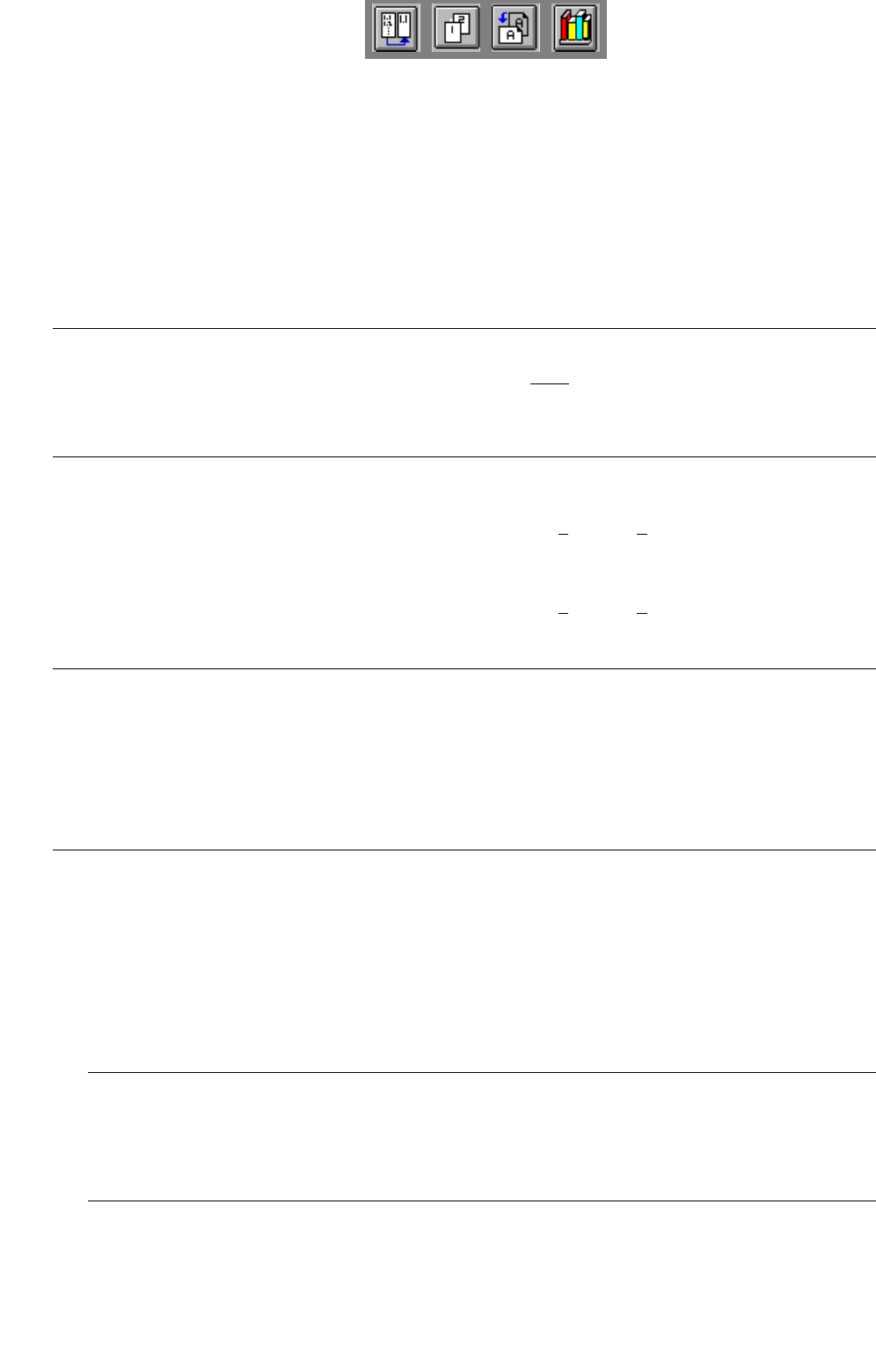
The component is displayed in its 0°-description in the view area of the Package Form Editor. Here, the origin
of the coordinate system is always located in the center of the view area. From there, the X-axis points to the
right, the Y-axis points upward. It is also possible to describe a component both in horizontal and in upright
position (see
Fig. 6.1.12). As a rule, the center of the component coincides with the zero point of the coordinate
system.
Fig. 6.1.12 0°-Description in the Package Form Editor
Legend pertaining to Fig. 6.1.12:
➀ Correct (display in the view area)
➁ Incorrect (display in the view area)
The 0°-description of the standard package form contained in the package form library (GF-Bibliothek) is sub-
ject to certain rules which should also be observed for the creation of customer-specific package forms. It can
thus be ensured that different programmers can work with uniformly defined package forms. In this way it is
possible to determine, for example, the pick-up angle at the station without having to check the 0°-description
in the Package Form Editor.
An incorrect 0°-description may result in pick-up or vision errors at the station.
To avoid such errors, the following rule should be observed:
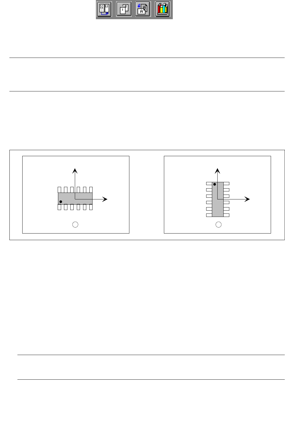
Rule: The long side of nozzles featuring rectangular suction areas is to be positioned along the
X-axis.
This means that die X-axis of the component points in the direction where the nozzle will make contact with the
long side of its suction area (see
Fig. 6.1.13).
Exception: special nozzles with 90°-displacement
Y
X
Y
X
Y
X
1 2
6 Product / Package Form User Manual Line Computer UNIX
6.1 Package Form Editor Software Version 502.xx 10/2000 Issue
212
I
t I I
Fig. 6.1.13 X-axis of the component is aligned with the long edge of the nozzle
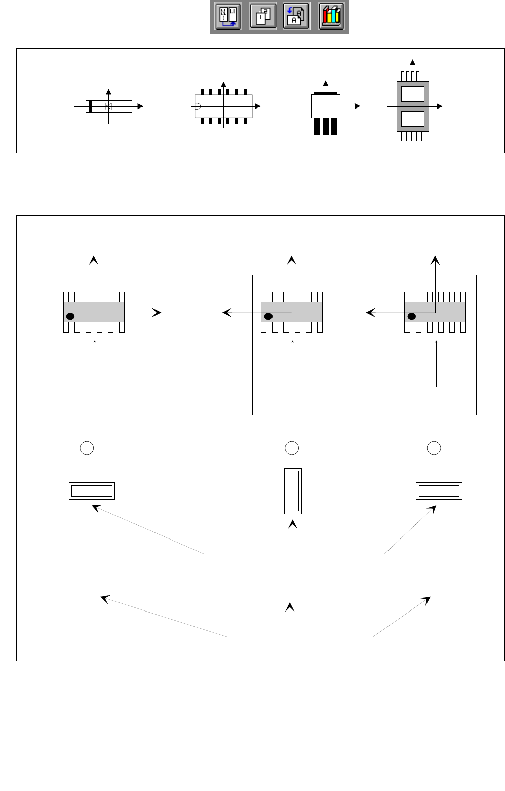
If the aforementioned rule is not observed, it may happen that the incorrect 0°-description will result in the errors
depicted below (see Fig. 6.1.14).
Fig. 6.1.14 0°-Description Errors
Y
X
Y
X
Y
X
Y
X
Y
X
Y
X
Y
X
0° 90° 0°
1 2 3
Correct
position of nozzle for picking up the component
transport
direction
transport
direction
transport
direction
Vacuum error
Vision system erro
r
Pick-up angle in the feeder (set-up)
0°-Description wrong0°-Description correct