SIPLACE Line Computer UNIX.pdf - 第231页
User Manual Line Computer UNIX 7 Product / Adhesive Pattern Software Vers ion 502.xx 10/2000 Issue 7.1 Adhesive Pattern Editor 229 I t I I 7 Product / Adhesive Pattern 7.1 Adhesive Patter n Editor For the various package…
6 Product / Package Form User Manual Line Computer UNIX
6.1 Package Form Editor Software Version 502.xx 10/2000 Issue
228
I
t I I
NOTE
If invalid values were entered, a dialog box containing a corresponding error message is displayed
(see page 6 - 193). The fields containing the invalid values are surrounded by a red frame. The dialog
box must first be acknowledged by clicking on OK. Thereafter, the entries can be corrected and con-
firmed by clicking on "OK".
Setting the Features of the Balls Within a Grid Group
The characteristic features of the balls of a selected grid group can be defined with the aid of the buttons
"El. connection" and "Centering fiducial" in the setting area of the "Model description" window (see Fig. 6.1.26).
- El. connection
If this button is activated, all balls of a selected grid group can be defined to be electrically conductive.
NOTE
By default, the button "El. connection" is automatically activated when the "Model description" window
is opened. This means that all balls within the grid groups are designated as an "El. connection", i.e.
they are electrically conductive. This setting can subsequently be changed for each individual grid
group.
Procedure:
● Select any ball from the grid group whose balls are to be defined as "electrically not conductive",
by double-clicking.
● Deactivate the El. connection button in the setting area.
Now, the balls of the selected grid group are not conductive.
- Centering fiducial
The selected grid group can be defined as an alignment structure for the determination of the position
of the component at the nozzle.
(This function is not implemented in the present software version).
Changing a Ball Model
NOTE
The procedure for changing the data of a defined ball model is the same as for changing a pin model
The relevant procedure is described on page 6 - 222.
User Manual Line Computer UNIX 7 Product / Adhesive Pattern
Software Version 502.xx 10/2000 Issue 7.1 Adhesive Pattern Editor
229
I
t I I
7 Product / Adhesive Pattern
7.1 Adhesive Pattern Editor
For the various package forms specific adhesive patterns (adhesive dot patterns) can be applied enabling the
components to be held (glued) securely on the PCB. The specific adhesive patterns for the various package
forms are defined with the aid of the Adhesive Pattern Editor.
7.1.1 Starting the Adhesive Pattern Editor
-
In the "programming mode" the Adhesive Pattern Editor is activated by clicking on the Adhesive
Pattern icon on the desktop.
- If the LC program was installed for the "control mode", the Package Form Editor can be started via the
"PRODUCT" menu on the desktop.
● Click on the Adhesive Pattern icon on the desktop (or the "Adhesive Pattern Editor" option on
the "PRODUCT" menu).
The FSB containing the ".dm" file is opened. This file contains all already-defined adhesive
patterns.
● Select adhesive pattern file ".dm" by double-clicking.
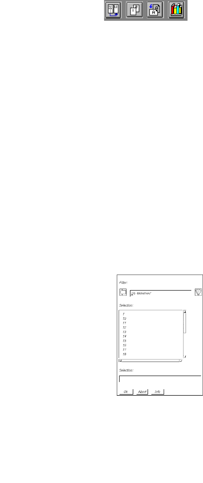
The following FSB containing the numbers of all previously defined adhesive patterns is displayed.
● Select adhesive pattern "xx" by double-clicking or enter new number on the keyboard and confirm
with OK. The main window containing the Adhesive Pattern Editor (see Fig. 7.1.1) is opened.
7 Product / Adhesive Pattern User Manual Line Computer UNIX
7.1 Adhesive Pattern Editor Software Version 502.xx 10/2000 Issue
230
I
t I I
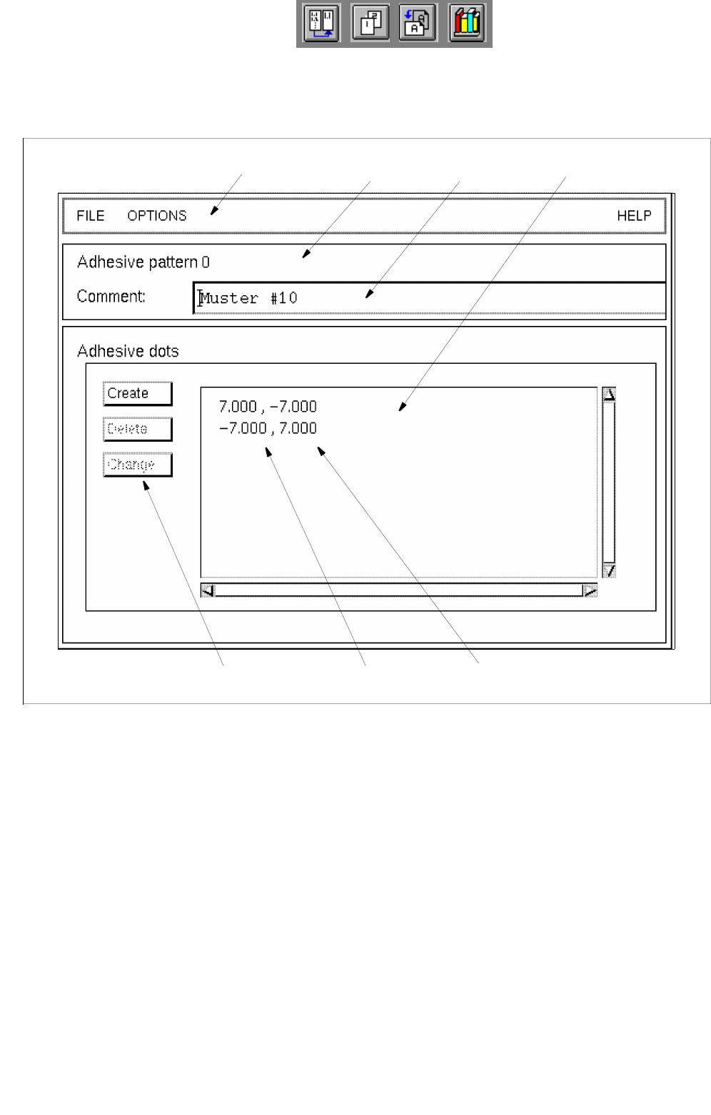
7.1.2 Main Window of Adhesive Pattern Editor
The areas of the main window and their functions are explained in the following.
Fig. 7.1.1 Main Window "Adhesive Pattern Editor"
The main window is subdivided as follows:
- Menu bar
- Title bar
- Editing field
- Command area
- Display area
menu bar title bar
editing field
x-coordinate
command area
display area
y-coordinate