SIPLACE Line Computer UNIX.pdf - 第236页
7 Product / Adhesive Pattern User Manual Line Computer UNIX 7.1 Adhesive Pattern Editor Software Version 5 02.xx 10/2000 Issue 234 I t I I
User Manual Line Computer UNIX 7 Product / Adhesive Pattern
Software Version 502.xx 10/2000 Issue 7.1 Adhesive Pattern Editor
233
I
t I I
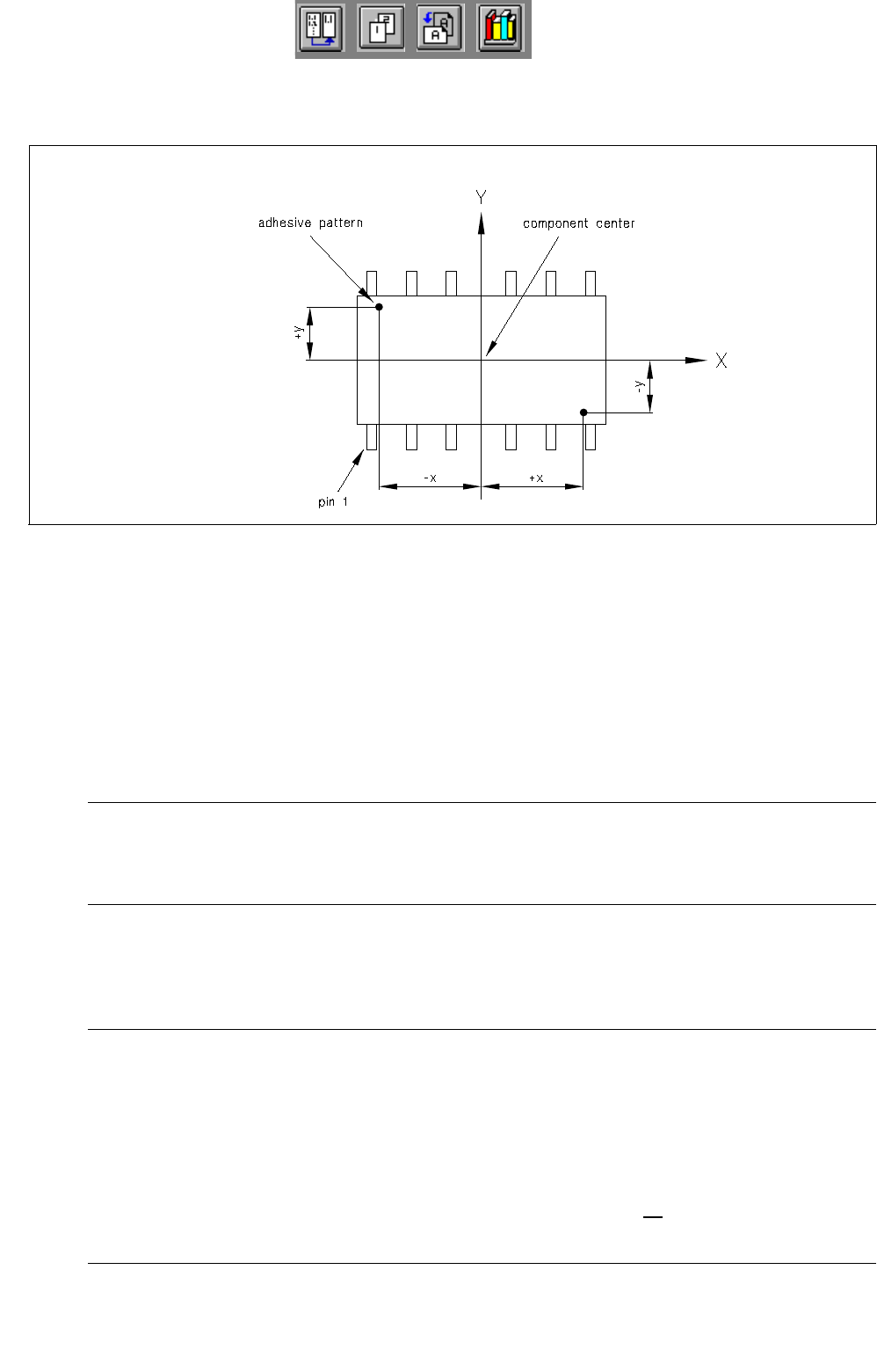
7.1.2.2 Definition of x/y-Coordinates for Adhesive Dots
Fig. 7.1.3 Definition of x/y-coordinates for adhesive dots
Editing a new adhesive dot
● Click on Create in the command area of the main window "Adhesive Pattern Editor" (see Fig. 7.1.1).
The window for editing the coordinate data of the new adhesive dot is opened (see Fig. 7.1.2).
● Click on editing field "X" and enter value for the x-coordinate (observe correct sign).
● Click on editing field "Y" and enter value for the y-coordinate (observe correct sign).
NOTE
In order to be able to apply the adhesive dots of an adhesive pattern by means of an adhesive
dispensing cartridge, a minimum spacing of the adhesive dots must be observed.
● Confirm the entries with OK.
The window is closed. The coordinate data of the created adhesive dot are displayed in the main
window "Adhesive Pattern Editor".
NOTE
If invalid values or characters (e.g. a comma as decimal point) were entered or if the minimum
distance between adhesive dots in an adhesive pattern has not been observed, a dialog box contai-
ning a corresponding error message is displayed. The fields containing the invalid values are sur-
rounded by a red frame. The dialog box must first be acknowledged by selecting OK. Thereafter, the
entries can be corrected and confirmed with OK.
The edited values are retained when the window is closed. If, however, no
saving operation is carried
out upon exiting the Adhesive Pattern Editor, the edited data will be lost.

User Manual Line Computer UNIX 8 Product / PCB
Software Version 502.xx 10/2000 Issue 8.1 PCB Editor
235
I
t I I
8 Product / PCB
8.1 PCB Editor
The PCB Editor enables the user to give a hierarchical description (pyramidal structure) of the PCB to be
assembled.
The PCB Editor is subdivided into the following sub-editors:
- Structure Editor
The Structure Editor provides the user with an overview of the overall structure of a PCB. It is
possible to create new PCB types and to edit existing ones.
As an option, the entire PCB including all placement positions, fiducials, ink spots, coordinate
systems, etc. can be represented graphically in the display area of the Structure Editor.
- Cluster Editor
The Cluster Editor serves to define or edit the basic data (cluster data) of a PCB.
- Placement Position Editor
The Placement Position Editor describes the location of the placement positions.
- Fiducial Editor
Fiducials, fiducial sets and ink spots can be defined or edited in the Fiducial Editor.