SIPLACE Line Computer UNIX.pdf - 第358页
12 Production Tools / Station and Line Con figuration User Manual Line Compu ter UNIX 12.1 Configuration Ed itor Software Version 502.xx 10 /2000 Issue 356 I t I I 12.1.2 Main Window of Configuration Editor (Structure Ed…
User Manual Line Computer UNIX 12 Production Tools / Station and Line Configuration
Software Version 502.xx 10/2000 Issue 12.1 Configuration Editor
355
I
t I I
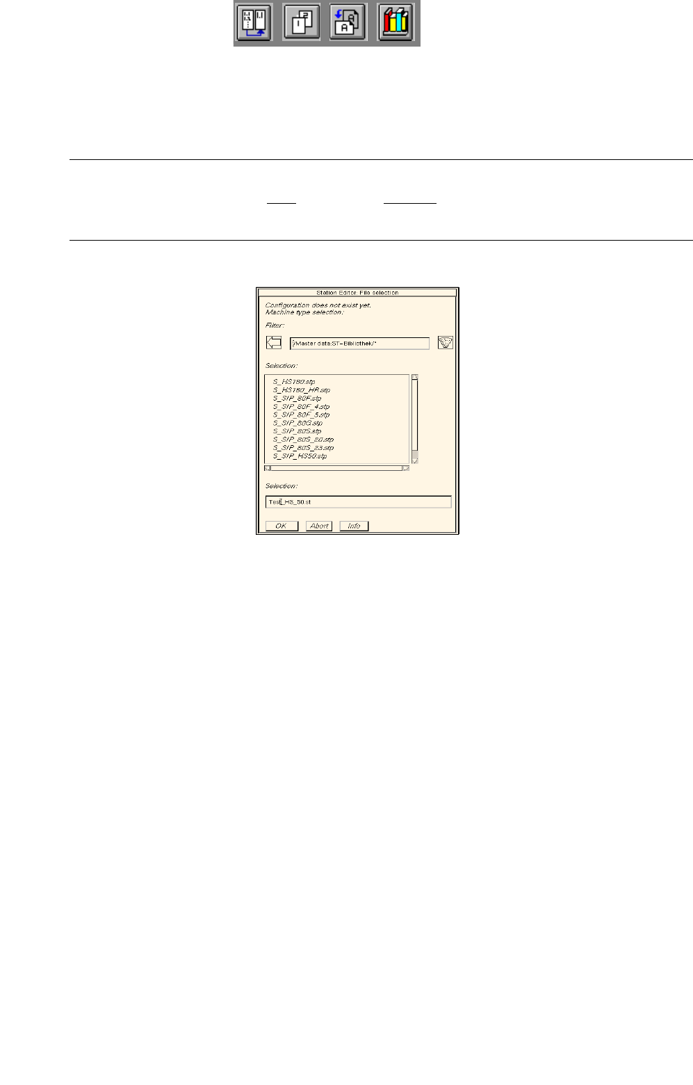
Generating a new configuration:
● Enter new station name "xx.st" and confirm with OK (or RETURN).
The FSB containing a listing of the machine types available for selection opens
(directory "master data:ST-Bibliothek").
NOTE
The station name may comprise max. 20 characters including the suffix ".st".
Some characters must not be used for the name, see chapt. 2, section 2.3 in this connection.
● Select machine type of the station entered and confirm with OK (or select machine type directly
by double-clicking).
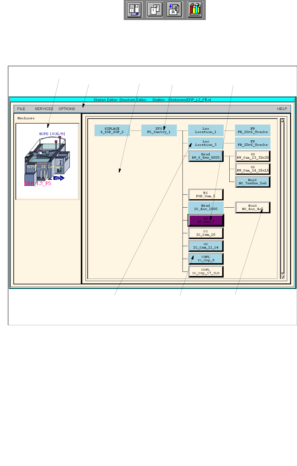
The main window of the Configuration Editor, the Structure Editor is opened (see
Fig. 12.1.1).
12 Production Tools / Station and Line Configuration User Manual Line Computer UNIX
12.1 Configuration Editor Software Version 502.xx 10/2000 Issue
356
I
t I I
12.1.2 Main Window of Configuration Editor (Structure Editor)
In the Structure Editor the maximum permitted configuration of the selected machine type is shown.
Fig. 12.1.1 Structure Editor (Machine Type "SIPLACE F5)
menu bar
fixed, non-changeable
machine option
allocated (set up) machine
option
unallocated machine
option (may be set up)
graphical display of the
station
selected, allocated machine optionlocation
display area

User Manual Line Computer UNIX 12 Production Tools / Station and Line Configuration
Software Version 502.xx 10/2000 Issue 12.1 Configuration Editor
357
I
t I I
The main window is subdivided as follows:
- Display area (for description refer to section 12.1.2.1)
- Menu bar The menu bar contains the "FILE", "SERVICES", "OPTIONS" and
"HELP" menus.
The "FILE" menu is described insection 12.1.2.4, the "SERVICES" menu
in section 12.1.2.5.
The "°Component changeover table" menu option of the "OPTIONS"
menu is described in section 12.1.2.6.
NOTE
Since the functions and operation of the "OPTIONS" and "HELP" menus are similar to those in other
application programs of the line computer, they are described comprehensively in chapt. 2.
12.1.2.1 Display Area of Structure Editor
In the display area of the Structure Editor the maximum possible configuration of the machine type is displayed
as a structure.
- Each rectangle (button) within the structure represents a machine option type.
- The machine option types are factory-defined. The original data of a machine option were defined in a
machine option type.
- A given machine option type can be the location for lower-level machine option types. These lower-
level machine option types are connected to the higher-level machine option type by means of lines.
- The topmost machine option type in the display area is the station. It is the location for lower-level
machine option types.
- Upon starting the Structure Editor the rectangle (button) of the topmost machine option type is
selected.
- If a button is clicked on that represents a feeder area or a placement head, then the position of the
relevant machine option is displayed in a graphical representation of the station (see Fig. 12.1.1).