SIPLACE Line Computer UNIX.pdf - 第359页
User Manual Line Computer UNIX 12 Production Tools / Station and Li ne Conf iguration Software Vers ion 502.xx 10/2000 Issue 12.1 Configuration Editor 357 I t I I The ma in window i s subdi vided as fo llows: - Display a…
12 Production Tools / Station and Line Configuration User Manual Line Computer UNIX
12.1 Configuration Editor Software Version 502.xx 10/2000 Issue
356
I
t I I
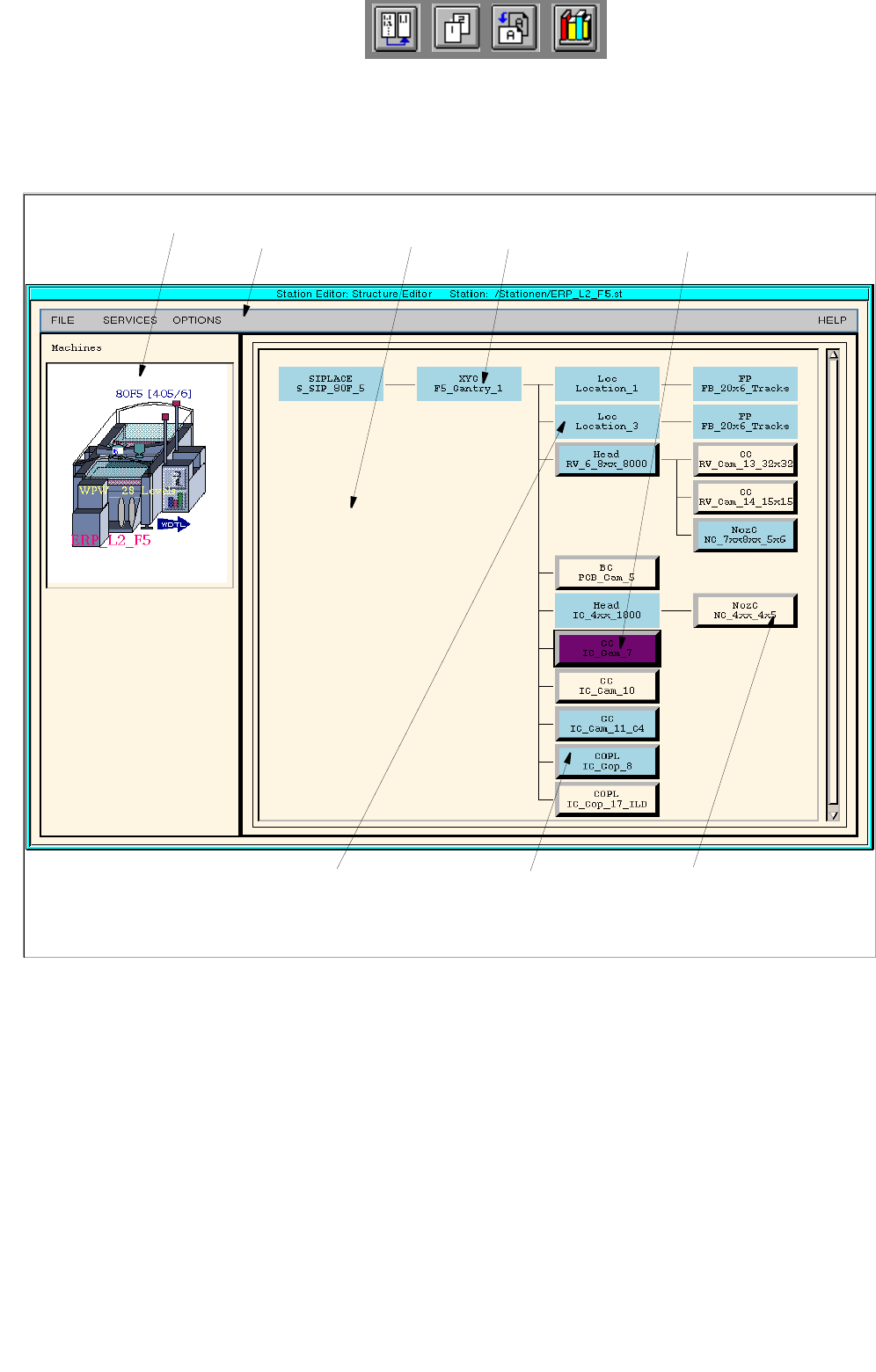
12.1.2 Main Window of Configuration Editor (Structure Editor)
In the Structure Editor the maximum permitted configuration of the selected machine type is shown.
Fig. 12.1.1 Structure Editor (Machine Type "SIPLACE F5)
menu bar
fixed, non-changeable
machine option
allocated (set up) machine
option
unallocated machine
option (may be set up)
graphical display of the
station
selected, allocated machine optionlocation
display area

User Manual Line Computer UNIX 12 Production Tools / Station and Line Configuration
Software Version 502.xx 10/2000 Issue 12.1 Configuration Editor
357
I
t I I
The main window is subdivided as follows:
- Display area (for description refer to section 12.1.2.1)
- Menu bar The menu bar contains the "FILE", "SERVICES", "OPTIONS" and
"HELP" menus.
The "FILE" menu is described insection 12.1.2.4, the "SERVICES" menu
in section 12.1.2.5.
The "°Component changeover table" menu option of the "OPTIONS"
menu is described in section 12.1.2.6.
NOTE
Since the functions and operation of the "OPTIONS" and "HELP" menus are similar to those in other
application programs of the line computer, they are described comprehensively in chapt. 2.
12.1.2.1 Display Area of Structure Editor
In the display area of the Structure Editor the maximum possible configuration of the machine type is displayed
as a structure.
- Each rectangle (button) within the structure represents a machine option type.
- The machine option types are factory-defined. The original data of a machine option were defined in a
machine option type.
- A given machine option type can be the location for lower-level machine option types. These lower-
level machine option types are connected to the higher-level machine option type by means of lines.
- The topmost machine option type in the display area is the station. It is the location for lower-level
machine option types.
- Upon starting the Structure Editor the rectangle (button) of the topmost machine option type is
selected.
- If a button is clicked on that represents a feeder area or a placement head, then the position of the
relevant machine option is displayed in a graphical representation of the station (see Fig. 12.1.1).
12 Production Tools / Station and Line Configuration User Manual Line Computer UNIX
12.1 Configuration Editor Software Version 502.xx 10/2000 Issue
358
I
t I I
12.1.2.2 Colors and Their Meanings in the Display Area of the Structure Editor
In the display area of the Structure Editor the buttons representing the individual machine option types are either
displayed without or with an outline (three-dimensional) and various colored backgrounds, depending on the
respective status.
Meanings of the various possibilities of representing the buttons:
- light blue, without outline The machine option is a fixed part of the station.
It may not be removed.
- light blue, three-dimensional The machine option is part of the station.
It may be removed again.
- white, three-dimensional The machine option is not yet a part of the station.
It may be allocated.
- violet Selected, already allocated or fixed machine option
- green Selected, unallocated machine option
12.1.2.3 Allocating and Deleting Machine Options
-
Allocate
To allocate machine options to a location, proceed as follows:
● Select unallocated machine option (three-dimensional white button) by double-clicking on it. The
machine option is now configured at the station. It is displayed as a three-dimensional, light blue
button.
CAUTION
To be able to allocate a machine option to a location, all higher-order (higher-level) machine options must
have already been set up.
Example: The RV nozzle changer may only be allocated if the RV head which is of a higher level within
the structure has already been set up.
NOTE
To be able to configure a waffle-pack changer (WPC) or a matrix-tray changer (MTC) at the station,
first the button for the relevant feeder area, or feeder location, needs to be clicked on and then the Feeder
Part Editor must be opened via the "Services" menu (see section 12.1.2.5).
In the Feeder Part Editor the WPC and MTC may be allocated via the options list (see chapt. 13.1, section
13.1.3.2).
Once the WPC or MTC has been set up in the feeder area, it will immediately be displayed in the Struc-
ture Editor in the graphical display of the station (see Fig. 12.1.1).