SIPLACE Line Computer UNIX.pdf - 第514页
16 MaDaMaS User M anual Line Computer UNI X 16.2 MaDaMaS Evaluation User Interfac e Software Version 5 02.xx 10 /2000 Issue 512 I t I I

User Manual Line Computer UNIX 16 MaDaMaS
Software Version 502.xx 10/2000 Issue 16.2 MaDaMaS Evaluation User Interface
511
I
t I I
16.2.9.1 "Last PCB" Evaluation
The "Last PCB" evaluation displays for the entire line and for each station of the line the minutes that have
elapsed since the time of completion (or abortion) of the last PCB.
If this time span, starting with the completion/abortion of the last PCB, exceeds the "Timeout" value preset under
Limit Values, the icon is displayed in the "Performance" chart (see
section 16.2.4.1). The station has
come to a standstill.
The "Last PCB" evaluation is of importance owing to the fact that the data will not be updated until a new PCB
has been completed. It is available for the entire line and for all placement stations.
- Calling up the "Last PCB" evaluation for the line
● On the menu bar select EVALUATIONS --> Overall view.
The "Overall view" evaluation is displayed.
The "Last PCB" evaluation for the entire line is displayed in the field below the "Performance"
chart (see
Fig. 16.2.1).
- Calling up the "Last PCB" evaluation for all stations
● On the menu bar select EVALUATIONS --> Performance.
Or else:
● Click on the blue bar in the "Performance" chart in the overall view.
The "Performance" chart is displayed for all placement stations.
The time that has elapsed since the completion/abortion of the last PCB is displayed for each
station in the field below the "Performance" chart (see
Fig. 16.2.9).

User Manual Line Computer UNIX 17 Practical Tips on Using the LC UNIX
Software Version 502.xx 10/2000 Issue 17.1 Introduction
513
I
t I I
Using three PCBs as an example, this chapter contains a description of all work steps required - from the ge-
neration of the placement programs through to job scheduling.
This chapter can be used as a beginner´s guide for the new operator and be worked through step-by-step, or
it can serve as a reference or a refresher section for experienced programmers. All this is accomplished by the
two-page concept with the left side containing only keywords and the right side describing each work step in
detail.
The chapter is intended as a supplement to the other chapters of the User´s Manual and therefore cannot an-
ticipate every possible circumstance that may be of interest. For further information about a topic or a function,
please refer to the corresponding chapter in the User´s Manual.
In addition, it is very helpful to use the On-Line Help systems available:
— On-line Bubble-Help: contains information about all editing fields, icons and window areas.
• Click on the Online Help On/Off option on the HELP menu.
• Move the mouse pointer to the location where you wish to obtain explanations.
A window containing the Help information is opened and closed again by moving the mouse pointer.
— Help Index: contains a description on how to proceed concerning almost all topics.
• Click on the Index option on the HELP menu.
The Help Index is opened.
• Search for a topic using the Text search function, or browse through the contents and descriptions on
the topics by clicking on the terms highlighted in green.
The PCBs described relate to different learning objectives:
• PCB 1: single circuit, with focus on the basic principle of the generation of placement programs;
• PCB 2: single circuit, with focus on the description of customer-specific package forms;
• PCB 3: complex circuit, with focus on cluster technique.
All examples are based on a given line and station configuration. Since the configuration differs from customer
to customer, the data given can be used as an example only and must be adapted by the customers to satisfy
their individual requirements.
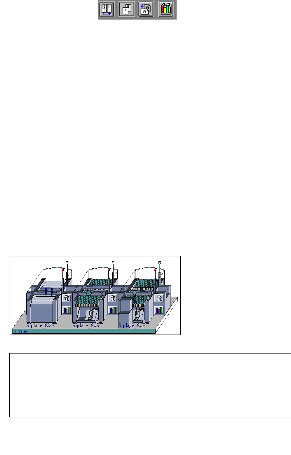
Station Configuration
17 Practical Tips on Using the LC UNIX
17.1 Introduction
Siplace_80G :
• optical PCB centering
Siplace_80S:
• optical PCB centering
• revolver head
• segment type 2 -> 6xx nozzles
• component camera 19x25 in head
-> sensor type 9
Siplace_80F:
• optical PCB centering
• IC-head -> 4xx nozzles
• IC-head camera -> sensor type 7
• revolver head
• segment type 2 -> 6xx nozzles
• component camera 19x25 in head
-> sensor type 9
• Waffle-Pack Changer
Line Configuration