SIPLACE Line Computer UNIX.pdf - 第566页
17 Practical Tips on Using the LC UNIX User Manual Line Computer UNIX 17.4 Set-Up Generat ion Software Version 502.xx 10/2000 Issue 564 I t I I FIL E Save FILE Quit 17.4 Set-Up Generation A comm on set-up is to be crea t…
User Manual Line Computer UNIX 17 Practical Tips on Using the LC UNIX
Software Version 502.xx 10/2000 Issue 17.3 Description of Components and PCBs
563
I
t I I
Entering placement positions: the entry of placement positions is dispensed with for the duplicate.
To save the PCB data, proceed as follows:
87. In the PCB Editor click on the Save option on the FILE menu.
The PCB data are saved.
88. Click on the Quit option on the FILE menu.
The PCB Editor is closed. The description of PCB 3 is completed.
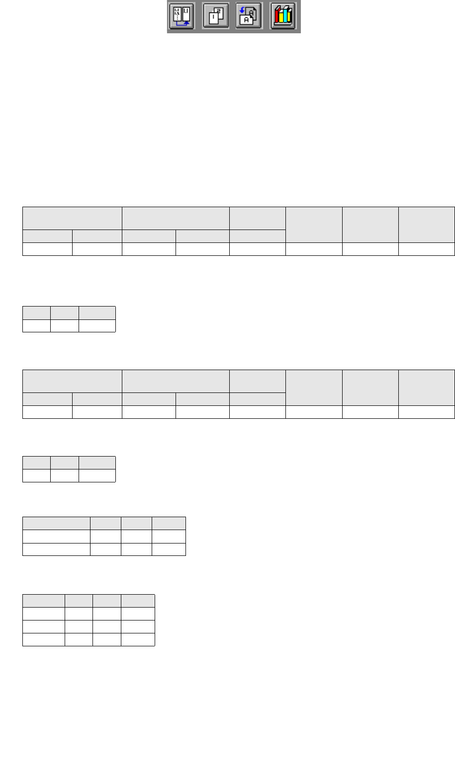
Have you entered all values correctly? Compare the solutions below (see also Fig. 17.3.7 on
page 17-553):
Di
mens
i
ons o
f
th
e
PCB
(
page
17
-
555)
Vector (0.0) -->
Corner_1:
Vector Corner_1 -->
Corner_2
PCB height
PP position
recognition
Ink spot
PCB
position
recognition
X Y X Y h
-5 -5 335 272 1.5 no no no
Offset values of the first cluster (page 17-557)
X Y Angle
10 10 0
Dimensions of the first cluster (page 17-557)
Vector (0,0) -->
Corner_1:
Vector Corner_1 -->
Corner_2
PCB height
PP position
recognition
Ink spot
PCB
position
recognition
X Y X Y h
0 0 150 116 no no yes
Offset values of the first single circuit (page 17-559
)
X Y Angle
15 15 0
Offset values of the duplicated single circuits (page 17-561)
Single circuit X Y ] Angle
board_2 60 15 0
baord_3 105 15 0
Offset values of the duplicated clusters (page 17-561)
Cluster X Y Angle
pattern_2 165 10 0
pattern_3 160 252 180
pattern_4 315 252 180
17 Practical Tips on Using the LC UNIX User Manual Line Computer UNIX
17.4 Set-Up Generation Software Version 502.xx 10/2000 Issue
564
I
t I I
FILE
Save
FILE
Quit
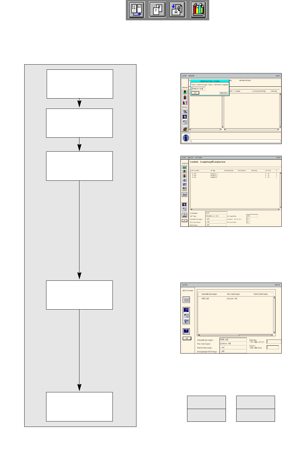
17.4 Set-Up Generation
A common set-up is to be created for the three PCBs.
17.4.1 Lot Handling
Opening the
optimization dialog
Creating lot file
Editing lot file
Generating basic
optimization data
Saving lot file
User Manual Line Computer UNIX 17 Practical Tips on Using the LC UNIX
Software Version 502.xx 10/2000 Issue 17.4 Set-Up Generation
565
I
t I I
To open the optimization dialog, proceed as follows:
1. Click on the Optimization dialog icon .
The optimization dialog is opened.
To create a lot file, proceed as follows:
2. Activate the Create icon .
A window is opened.
3. Click on the editing field and enter a name for the lot file, here: Examples.lose.
4. Click on the OK button.
Job Control is opened.
To edit a lot file, proceed as follows:
5. In Job Control activate the Create icon , then activate the Edit support icon .
The Edit support Lot Data is opened.
6. Select the PCB you wish to edit by double-clicking, here: Example_1.la .
The PCB is transferred to the Selection: field.
7. Click on the Abort button, the other data are not used at this point.
Edit support is closed. The selected PCB is transferred to the editing area.
8. In the editing area click on the Lot name field and enter the lot name, here: ex1.
9. In the editing area click on the Lot size field and enter the lot size, here: 10.
10. In the editing area click on the Lot type field and enter the lot type, here: F.
11. Click on the OK button.
The job is transferred to the lot file. In the case of faulty entries, the respective field is surrounded by a red
frame and an error message is displayed above the list. Correct the entry.
12. Insert the remaining PCBs analogously, here: Example_2.la and Example_3.la, see chart.
To create the basic optimization data, proceed as follows:
13. Click on the Basic Optimization Data... command on the SERVICES menu.
The Basic optimization data window is opened.
14. Activate the Create icon and then activate the Edit support icon .
The Edit support Basic Optimization Data is opened.
15. Select the line, here: SMT.AK, and the subline, here: Linie.VA, by double-clicking.
16. Click on the Abort button, no fixed or initial set-ups are used here. The edit support is closed.
The selected data are transferred to the editing area.
17. Click on the OK button.
The data are transferred to the list.
18. Click on the Quit command on the FILE Menu.
A dialogbox containing a request for saving data is opened
19. Click on the Yes button.
The Basic optimization data window is closed, the data are saved.
To save the lot file, proceed as follows:
20. Click on the Save command on the FILE menu.
The lot file is saved in the Job Data under the entered name.
21. Click on the Quit command on the FILE menu.
Job Control is closed. The Optimization Dialog is opened.
PCB Lot name Lot size
Lot
type
Example_1.la ex1 10 F
Example_2.la ex2 13 F
Example_2.la ex3 16 F