IPC J-STD-003B.pdf - 第37页
APPENDIX D Test Protocol for Wetting Balance Gauge Repeatability and Reproducibility (GR&R) Using Copper Foil Coupons 1. All coupons for these tests shall be prepared individu- ally just prior to testing. Do NOT batc…

APPENDIX C
Informative Annex
C.1 Test Equipment Sources
The equipment sources described below represent those
currently known to the industry. Users of this document are
urged to submit additional source names as they become
available, so that this list can be kept as current as possible.
C.1.1 Edge Dip Solderability Test Apparatus
GEN3 Systems Limited (Formerly Concoat Systems) Unit
B2, Armstrong Mall, Southwood Business Park, Farnbor-
ough, Hampshire GU14 0NR England. 011 44 12 5252
1500, www.gen3systems.com
HMP Soldermatics, P.O. Box 948, Canon City, CO 81212,
(719) 275-1531.
Robotic Process Systems, 23301 E. Mission Ave., Liberty
Lake, WA 99019, (509) 891-1680.
Solderability Testing and Solutions Inc., 18 Wildrose Dr.,
Edgewood, KY 41017, (859) 331-0598), www.wetting-
balance.com
C.1.2 Rotary Dip Test Apparatus
Robotic Process Systems, 23301 E. Mission Ave., Liberty
Lake, WA 99019, (509) 891-1680.
C.1.3 Wetting Balance Test Apparatus
GEN3 Systems Limited (Formerly Concoat Systems) Unit
B2, Armstrong Mall, Southwood Business Park, Farnbor-
ough, Hampshire GU14 0NR England. 011 44 12 5252
1500, www.gen3systems.com
Malcomtech 26200 Industrial Blvd, Hayward CA 64545,
510-293-0580, www.malcomtech.com
Metronelec, 54, Route de Sartrouville - Le Montreal 78232
Le PECO Cedax, France (USA Distributor/Solderability
Testing and Solutions Inc., 18 Wildrose Dr., Edgewood,
KY 41017, (859) 331-0598), www.wettingbalance.com
Robotic Process Systems, 23301 E. Mission Ave., Liberty
Lake, WA 99019, (509) 891-1680.
C.2 Consumable Product Sources
C.2.1 Test Flux Product Sources
The Test Flux product sources described below represent
those currently known to the industry. Users of this docu-
ment are urged to submit additional product source names
as they become available, so that this list can be kept as
current as possible.
AIM Solder {www.aimsolder.com} - Standard Flux #1
Product ID: RMA 202-25
GEN3 Systems Limited {www.gen3systems.com} - Prod-
uct ID’s: SMNA - Standard Flux #1: Actiec2/-Standard
Flux #2: Actiec 5
Kester {www.kester.com} - Standard Flux #1 Product ID:
182
Qualitek International, Inc. {www.qualitek.com} - Stan-
dard Flux #1 Product ID: 285-25
Solderability Testing and Solutions Inc. {www.wettingbal-
ance.com} - Standard test flux 0.2% and Standard test flux
0.5%
C.2.2 Gage R&R Test Coupon Product Sources
The copper coupons required for the Gage R&R testing in
Appendix D shall be acid copper electroplated foil, HTE
grade (conforms to IPC-4562/3 - CU-E3), but they shall
have NO conversion coatings applied.
(NOTE: The coupons will/should look stained and oxi-
dized.)
The copper coupon can be of any of the three following
dimensions, AABUS:
• 10 mm x 10 mm X 35µµm thick foil (1 oz nominal)
• 5 mm x 10 mm x 35 µm thick foil (1 oz nominal)
• 2 mm X 10 mm X 35 µm thick foil (1 oz nominal)
Solderability Testing and Solutions Inc. {www.wettingbal-
ance.com} is one source of these Gage R&R test coupons.
IPC J-STD-003B March 2007
26
Copyright Association Connecting Electronics Industries
Provided by IHS under license with IPC
Not for Resale
No reproduction or networking permitted without license from IHS
--`,,```,,,,````-`-`,,`,,`,`,,`---
//^:^^#^~^^"^~"^"^:$^~#:"#:$@:~^"$^:#*~^$^~:^#*^^:^^*\\

APPENDIX D
Test Protocol for Wetting Balance Gauge Repeatability
and Reproducibility (GR&R) Using Copper Foil Coupons
1. All coupons for these tests shall be prepared individu-
ally just prior to testing. Do NOT batch clean the
samples.
2. Copper foil of 35 microns nominal thickness (‘‘1 oz’’
copper) shall be used for the test.
3. The copper foil shall have NO surface treatment and
is expected to have an oxidized appearance upon
receipt from the supplier. Do not use the copper foil if
it is bright and shinny. This is indicative of surface anti
tarnish treatments being used. Surface treatments/
preservatives can interfere with the ability to make a
consistent ‘‘known good coupon’’ necessary for this
test.
4. The copper foil coupons shall be die cut to ensure
repeatability of the samples being tested and shall be
of the following width dimensions;
a. 2 mm
b. 5 mm
c. 10 mm
5. Create a file for each foil width and for each individual
person that is involved performing the GR&R.
6. Test parameters shall be:
a. Solder temperature shall be the as recommended
for the alloy and the specification being used, i.e.,
for SnPb and ANSI-J-STD-003 it shall be 235 °C,
for ANSI-J-STD-002 it shall be 245 °C. For SAC
305 it shall be 255 °C, regardless of the specifica-
tion.
b. Immersion depth shall be 0.4 mm.
c. Immersion speed shall be 2 mm/sec.
d. Dwell time in the solder shall be 10 seconds.
e. Immersion angle shall be 90 degrees incident to the
solder.
f. No preheat shall be used.
7. Sample preparation for the ‘‘known good coupon’’
shall be as follows:
a. Use a tweezers to immerse a foil sample into a bea-
ker of Acetone and gently agitate for 20 seconds.
b. Remove sample and blot both sides dry with ‘‘Kim
wipes’’ or other suitable lab tissue.
c. Again using a tweezers, immerse the above sample
into a 20% v/v Nitric acid solution and gently agi-
tate for 20 seconds.
d. Immerse the sample immediately into DI water and
gently agitate for 20 seconds.
e. Blot the sample dry as in step ‘‘b’’ above.
8. Dip sample into the ‘‘standard activated flux’’ nor-
mally used for solderability testing for 5 seconds.
9. Holding the samples vertically, blot to remove excess
flux.
10. Place sample into tool holder.
11. Run the test.
12. Repeat ten times for each foil width and each test per-
son. It is recommended that three people should be
used for the GR&R study.
13. For ease of data manipulation it is recommended to
convert the wetting forces obtained into mN/mm of
wettable length. For the 10 mm coupon for example,
the wettable length is 2 times 10 mm plus 2 times
0.035 mm for a total length of 20.07 mm.
14. For the ‘‘standard activated’’ flux of nominal 0.2%
activation, the wetting force used for the calculations
shall be 0.31 mN/mm. If a more active flux is being
used, a large sample shall be run to obtain the mean
value and this used for the calculations.
15. Calculate the standard deviation for each of the foil
widths and the people running the test.
16. Multiply the standard deviation value by 6 (this repre-
sents the plus - minus 3 standard deviations of a nor-
mal distribution)
17. Divide this number by 0.31 and multiply by 100 to
obtain a percentage value.
18. Tabulate the three values per person.
19. For an acceptable GR&R, the values obtained should
be below 10%.
20. There should be excellent R&R results with the 10 mm
coupon the first time this protocol is performed with an
increasing spread test person to test person when using
the smaller coupons. You may have to repeat the test
or allow the individuals some ‘‘practice time’’ prior to
running the full GR&R.
21. In addition to testing the individual, this protocol also
tests the machine and will show linearity and any bias
if it exists. Because the wetting forces have been nor-
malized to mN/mm, the readings for each coupon
width should be the same. If they are clearly different
but the standard deviations produced by the individual
test people are below 10%, then there is a problem
with the wetting balance and you should contact the
manufacturer.
March 2007 IPC J-STD-003B
27
Copyright Association Connecting Electronics Industries
Provided by IHS under license with IPC
Not for Resale
No reproduction or networking permitted without license from IHS
--`,,```,,,,````-`-`,,`,,`,`,,`---
//^:^^#^~^^"^~"^"^:$^~#:"#:$@:~^"$^:#*~^$^~:^#*^^:^^*\\
APPENDIX E
J-STD-002/J-STD-003 Activated Solderability
Test Flux Rationale Committee Letter
The current J-STD-002/J-STD-003 specification includes a
departure in the test flux methodology used in past solder-
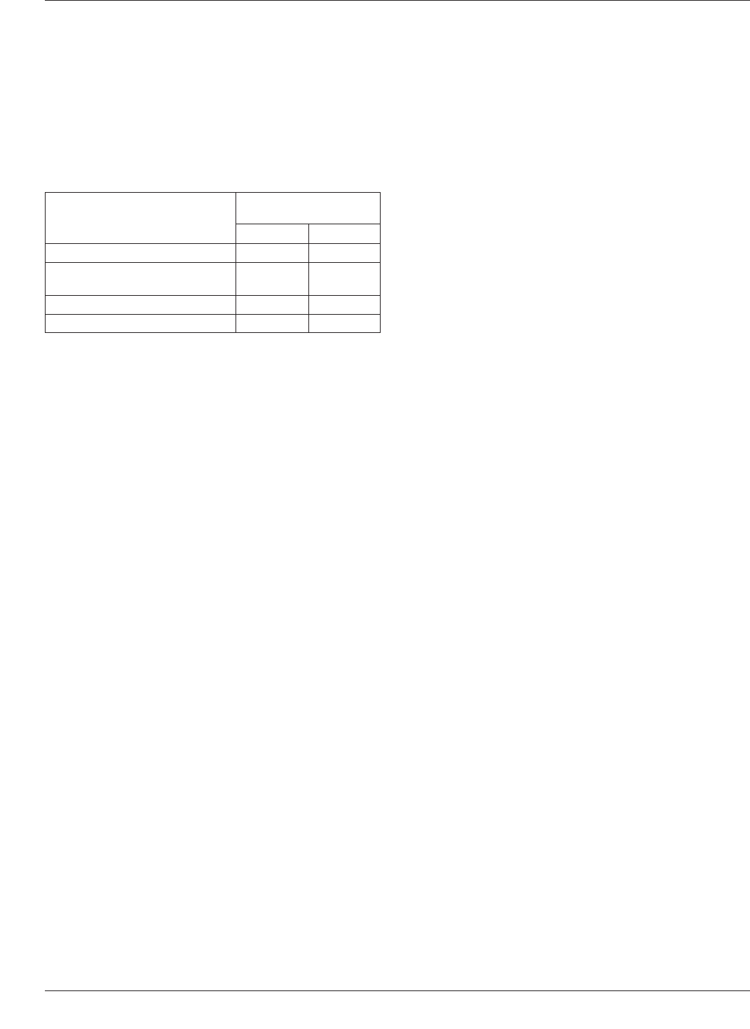
ability testing. The table in 3.2.2 Flux is:
The J-STD-002/J-STD-003 committees understood that
any proposed change to the use of ROLO (formerly desig-
nated type R) would be heavily scrutinized and would
require test data showing the applicability of using a stan-
dard activated flux composition. The J-STD-002/J-STD-
003 has spent significant resources working this flux
change issue, discussing the chemistry details and conduct-
ing multi-company Design of Experiment investigations.
The J-STD-002 committee chairmen, Dave Hillman [Rock-
well Collins], Doug Romm [Texas Instruments], Mark
Kwoka [Intersil], Jack McCullen [Intel], feel that the com-
mittee has compiled a significant data set and held through
topic discussions supporting the proposed flux material
change. The four rationales for proposing/supporting the
flux change are summarized below:
1) A Proactive Solderability Testing Approach To The
Implementation of Non-Tin Finishes
A number of industry studies (1996 NEMI Surface Fin-
ishes Task Group Report, 1997 NCMS Lead-Free Solder
Project, 2000 National Physical Laboratory CMMT (A)
284 Report) have shown that an incompatibility of ‘‘R
type’’ flux with non-tin surface finishes such as palla-
dium, organic solderability preservatives (OSPs), and
immersion gold. The introduction of these various
metallic surface finishes on components and printed wir-
ing boards is no longer the exception but has/is quickly
becoming the norm. The use of a ‘‘R type’’ flux contain-
ing only naturally occurring activators has resulted in
producing ‘‘false negative’’ solderability test results
which impact both the component/board fabricator and
the assembler negatively in terms of cost and schedule.
2) Reduced Solderability Test Variability
The J-STD-002/003 solderability committees enlisted
the assistance of Dr. Carol Handwerker and the
resources of the National Institute of Standards & Tech-
nology (NIST) to investigate/compare a standard acti-
vated flux composition versus the ‘‘R type’’ flux compo-
sition. A detailed statistical analysis by Bill Russell,
Raytheon Systems, and NIST statisticians revealed the
use of a standard activated flux composition greatly
reduced the amount of solderability test variation. One
of the major goals of the J-STD-002/003 solderability
committees is to develop test methods and standards
which promote consistency across the industry.
3) Concerns of A Loss of Solderability Assessment
Safety Margin
The two major historical rationale for using an ‘‘R
type’’ flux: 1) colophony or rosin contains only naturally
occurring flux activator constituents and thus is not sub-
jected to the problems/complications of chemistry for-
mulas by the flux supplier; 2) it was an accepted indus-
try acknowledged fact that if a component or printed
wiring board surface was found to have acceptable sol-
derability test results using ‘‘R type’’ flux then the more
active flux formulations used in the assembly process
would produce acceptable solder process results. This
solderability assessment safety margin was a self
imposed, industry consensus decision. The J-STD-002/
003 committees understood the historical relevance
behind the decision to use ‘‘R type’’ flux and had a
equally strong desire to maintain a solderability assess-
ment safety cushion. However, committees fielded a
number of industry inputs to reassess the solderability
flux composition based on the technology improvements
in surface finishes, improvements in the flux chemistry
formulations from flux suppliers, and the desire to not
have excessive safety margin which would impact cost
and schedule in an non-value added manner. The com-
mittees conducted a number of tests (Wenger, Kwoka,
ACI) demonstrating, using a specific standard level of
activation on real world, industry supplied component
and printed wiring board cases, that the occurrence of a
‘‘false acceptable’’ solderability test result was
extremely low. There was no case that exhibited a ‘‘pass
ROL1 test - fail ROL0 test - Fail during board assembly
‘‘sequence. In fact the use of both ROL1 and ROL0 are
more likely to create a ‘‘false reject ‘‘dip and look sol-
derability test result when compared to board level sol-
dering performance.
4) Standardization of Solderability Test Flux Composi-
tion On A Global Scale
A second major goal of the J-STD-002/003 solderability
committees is to develop test methods and standards
Table 3-1 Flux Composition
Constituent
Composition by
Weight Percent
Flux #1 Flux #2
Colophony 25 ± 0.5 25 ± 0.5
Diethylammonium hydrochloride
(CAS 660-68-4)
0.15 ± 0.01 0.39 ± 0.01
Isopropyl Alcohol (IPA) Balance Balance
Weight of Chlorine as % of solids 0.2 0.5
IPC J-STD-003B March 2007
28
Copyright Association Connecting Electronics Industries
Provided by IHS under license with IPC
Not for Resale
No reproduction or networking permitted without license from IHS
--`,,```,,,,````-`-`,,`,,`,`,,`---
//^:^^#^~^^"^~"^"^:$^~#:"#:$@:~^"$^:#*~^$^~:^#*^^:^^*\\