YSH20_Ope_E.pdf - 第101页
2-44 2 asic operation n Pitch movement T he camera can be moved at a specified pitch eac h time an arrow key on the [Mov e Pitch] tab is pressed. T he center of component can be tracked b y using pitch movement correct…
2-43
2
asic operation
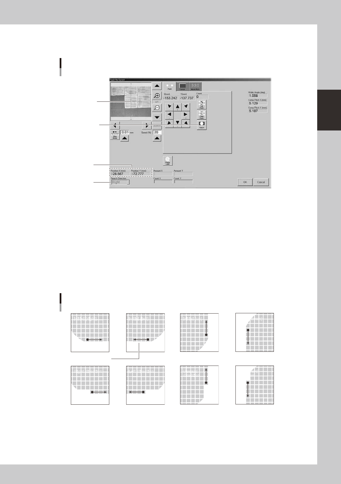
4. Position teach (current)
1
Press the [PosTch] button.
Align the center of
component with the
center of cross hairs.
Press this button to
determine the position.
Current position
Teach screen
Position teach
Search direction
24237-H0-00
2
Move to the first component.
Use the arrow keys to move to the first component.
3
Teach the center of the component.
Using multi-point teaching, teach the center of the first component on the basis of the orientation flat.
4
Check the teaching result.
When a new component was used, the XY position (current position) is usually set to 0.00 (center of
dicing frame). After the current position is correctly taught, the corresponding coordinates are
displayed in the XY positions.
5
Check the search direction.
Change the search direction as needed.
Search direction
Initial (right) Initial (left) Initial (up) Initial (down)
Right direction Left direction Upward
direction
Downward
direction
Orientation flat
23238-H0-00
6
Register the position.
Press the [OK] button. The "Current Teach" screen closes and the current position is registered in the
"Current Pos. X" and "Current Pos. Y" parameters.
2-44
2
asic operation
n
Pitch movement
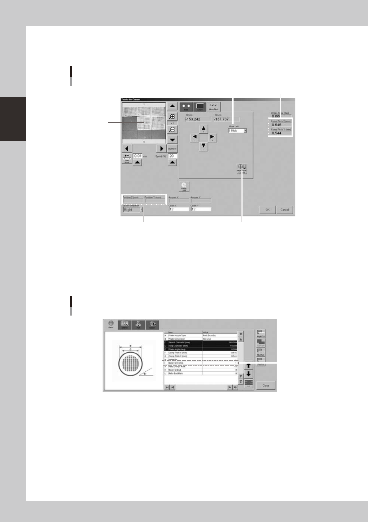
The camera can be moved at a specified pitch each time an arrow key on the [Move Pitch] tab is pressed. The center of
component can be tracked by using pitch movement correction.
This button should be pressed.
Current position
Teach screen
Pitch movement
Currently set pitch
Move Unit (pitch to move)
Center of cross
hairs moves to
center of component
each time a pitch
movement is
performed.
24240-H0-00
"Move Unit" (pitch to move)
The default is "1 Pitch" but "2 Pitch" and "5 Pitch" can also be selected.
[Pitch Move Correct] button
When this button is pressed, the component position is recognized during pitch movement and is displayed in the center
of the screen. To enable pitch movement correction, a mark number must be set in the "I: Mark For Comp." parameter on
the [Basic] tab of the "Wafer Information" screen.
Set this parameter.
Wafer information
"Mark For Comp." parameter
24241-H0-00
2-45
2
asic operation
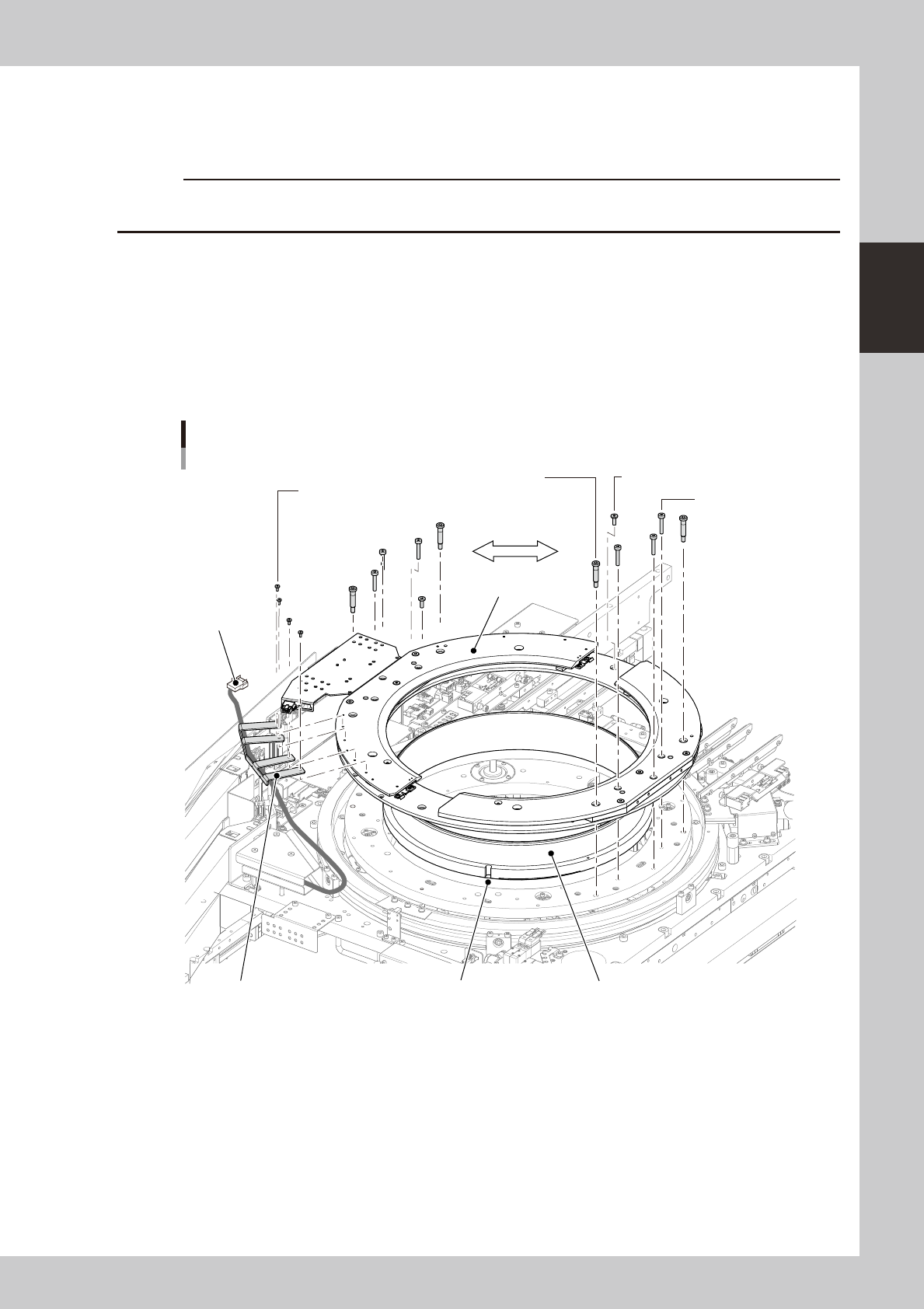
4.2.5 Exchanging the expander unit and pallet clamp
When changing the magazine size (dicing frame size) for the wafer tray changer, the expander unit and pallet
clamp must also be exchanged. The methods for exchanging them are described below.
c
machine. The machine may malfunction if the power is not turned off.
n
Expander unit
1
Turn off the power to the machine.
2
Disconnect the harness (connector).
1. Open the safety cover on the rear of the machine.
2. Unplug the connector (PLT STG) shown below.
3. Using a 1.5mm wrench, remove the bolts (4 bolts) that secure the harness bracket.
Exchanging the expander unit
Stud bolt
(4mm wrench.)
Mounting bolts are
symmetrically used.
Mounting bolt / 5-10 (3mm wrench)
Harness bracket mounting bolt
(1.5mm wrench.)
Connector
(PLT STG)
Mounting bolt / 5-25
(3mm wrench)
Attachment
Expand ringPositioning notchHarness bracket
23239-H0-00
3
Remove the bolts that secure the attachment.
1. Remove the stud bolts with the 4mm wrench (see the above figure).
2. Remove other mounting bolts with the 3mm wrench.