YSH20_Ope_E.pdf - 第45页
1-9 1 Part names and functions 4. Head assembly The head assemblies are mounted on two XY axes located on the A and B tables of the machine and move to pick up and place components. Head Fiducial camera Lighting unit (ca…
1-8
1
Part names and functions
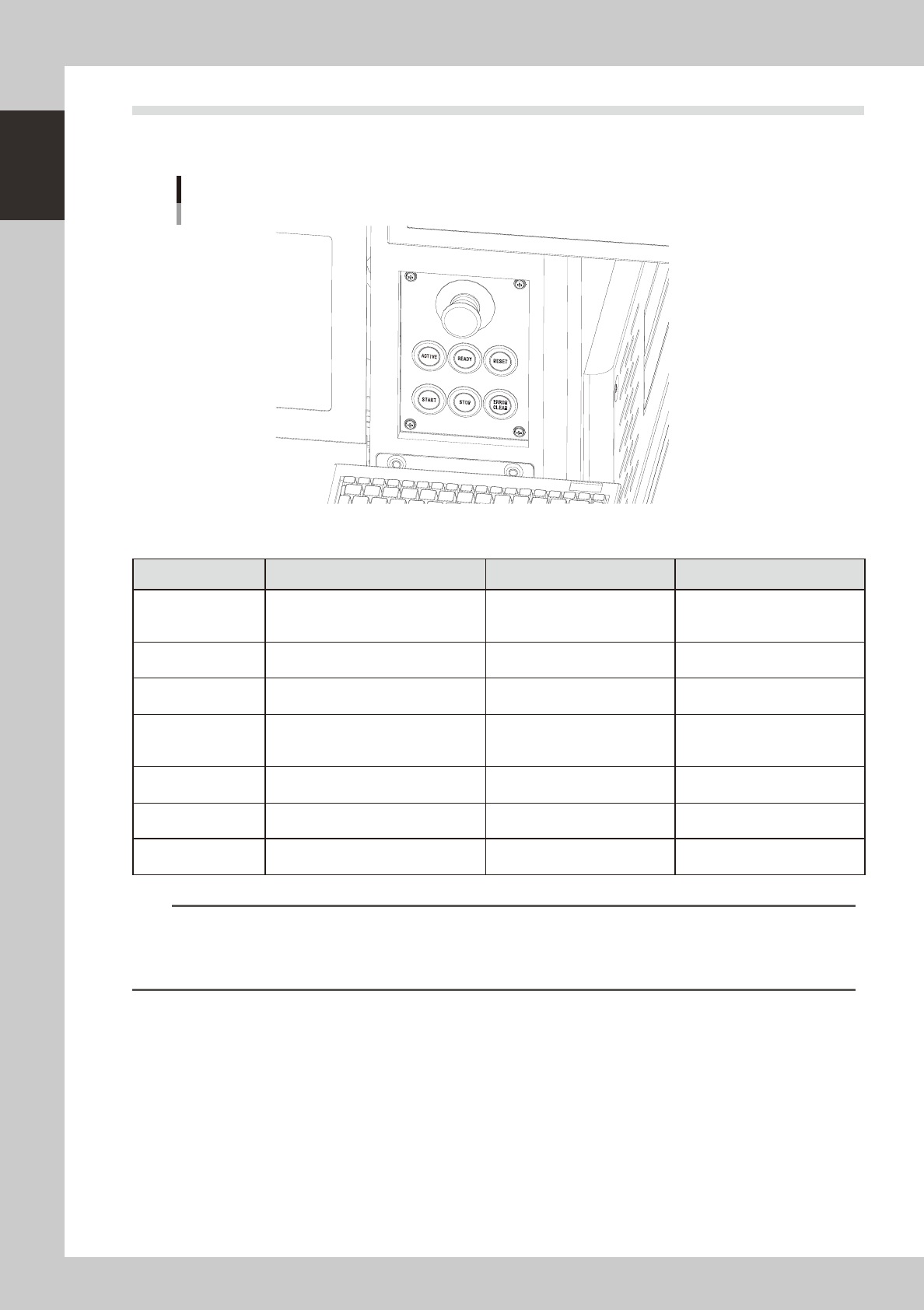
3.2 Operation panel buttons
The operation panel buttons are provided on the front and rear of the machine to run major commands
frequently used to operate the machine. Each button is lit while turned on.
Operation panel buttons
23111-H0-00
n
Operation panel button functions
Button name Use the button to: OFF ON
ACTIVE
Enable other keys. (The front and rear
[ACTIVE] keys cannot be turned on
simultaneously.)
• After machine has started.
• The other table has access
rights to operate machine.
• Has access rights to
operate machine.
READY
Release emergency stop and turn the
servo on.
• SERVO OFF
(Motor power OFF)
• SERVO ON
(Motor power ON)
RESET
Stop automatic operation and return to
standby for board production.
• Machine is in normal operation
or stopped.
• Machine has been reset.
START (green)
Perform component placement
according to board data.
• Machine is stopped.
• Machine is in normal operation.
[Flash]
Pause or step operation
STOP (Red)
Interrupt automatic operation. (Press
START to resume operation.)
• Machine is in normal operation. • Error occurred.
ERROR CLEAR
(Yellow)
Stop buzzer sound and clear error
screen.
• Machine is in normal operation. • Error occurred.
EMERGENCY STOP
Trigger emergency stop. Turn to the
right to release it.
n
NOTE
The [ACTIVE] button is provided on both front and rear (option) panels, but cannot be turned on simultaneously. This
means that the [READY], [START], [ERROR CLEAR] and [RESET] buttons are enabled only when the [ACTIVE] key on the
same panel is turned on. (The [STOP] button can be used when the [ACTIVE] button is either on or off.)
The keyboard is enabled only when the [ACTIVE] key on the front panel is on.
1-9
1
Part names and functions
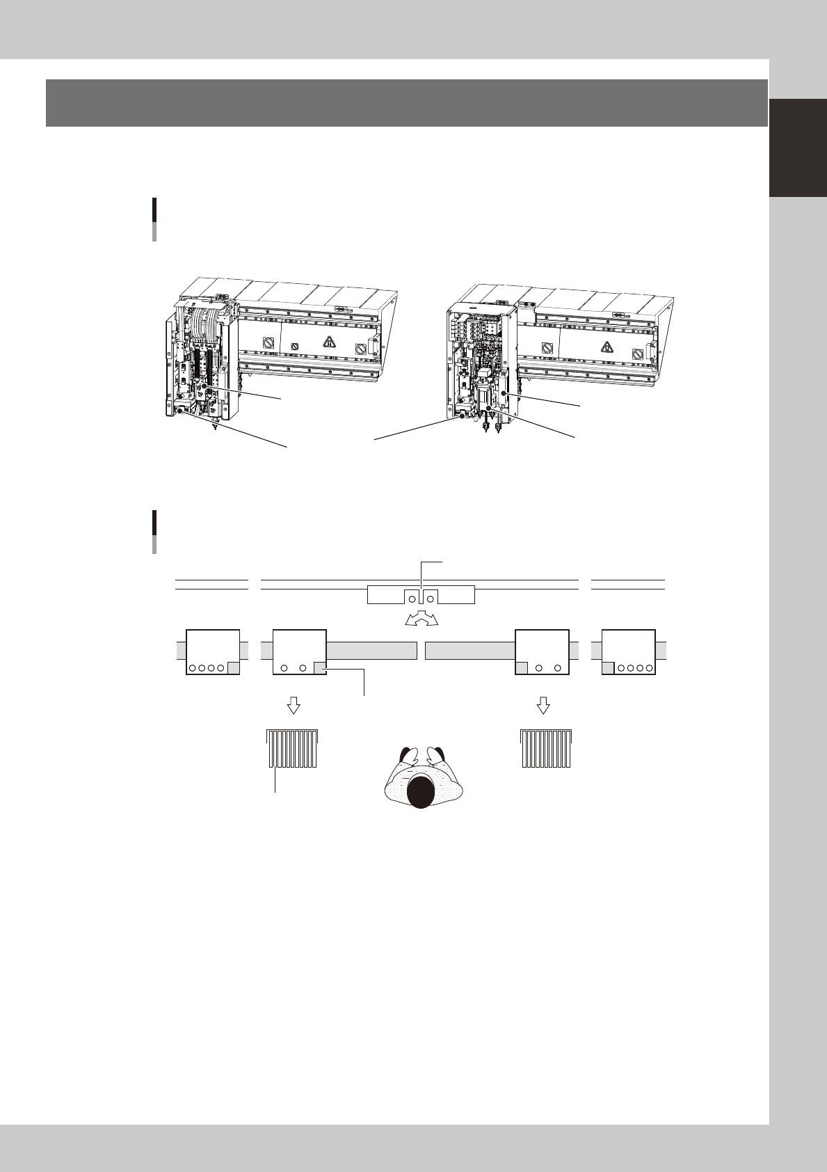
4. Head assembly
The head assemblies are mounted on two XY axes located on the A and B tables of the machine and move to
pick up and place components.
Head
Fiducial camera Lighting unit
(camera axis is optional)
Head (dual head)
Head slide handle
FF head 4M head
Head (4 in-line heads)
23112-H0-10
BB
AA
Head layout
1 10 101 110
Front of machine
1 2 3 41 2 3 4 1 21 2
Wafer head
4M head FF head
Fiducial camera
Tape feeder
23113-H0-10
1-10
1
Part names and functions
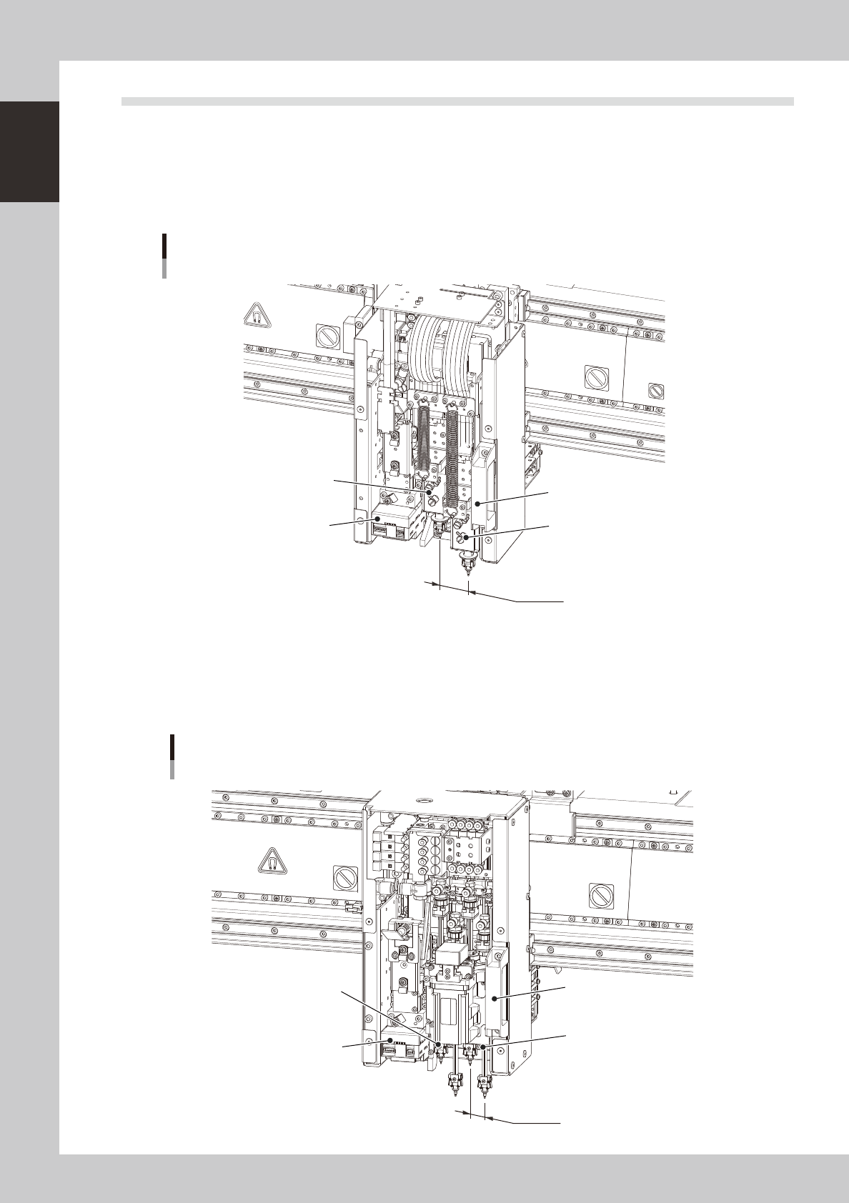
4.1 Component pick-and-place head
4.1.1 F head
The F head assembly has two pick & place heads and is mounted for each table, which are capable of load
control. On both tables, the left head is designated Head 1 and the right is Head 2, as viewed from the front of
the machine. The spacing between each head is 36mm which is identical with the nozzle pitch of the wafer
tray changer.
Head 2
36mm
Head 1
Head slide handle
Fiducial camera
F head (load control)
Example of A-table
23114-H0-00
4.1.2 4M head
The 4M head assembly has 4 in-line heads and is mounted for each table. On both tables, head numbers are
designated from 1 to 4, from the left as viewed from the front of the machine. The spacing of adjacent nozzles
attached to the head assembly is 18mm.
Head 4
18mm
Head 1
Head slide handle
Fiducial camera
4M head
Example of A-table
23114-H0-00