YSH20_Ope_E.pdf - 第47页
1-11 1 Part names and functions 4.1.3 Component recognition cameras T he YSH20 has one component recognition camera (multi-vision camera) on either the front or rear of eac h stage. An optional multi-vision camera or sin…
1-10
1
Part names and functions
4.1 Component pick-and-place head
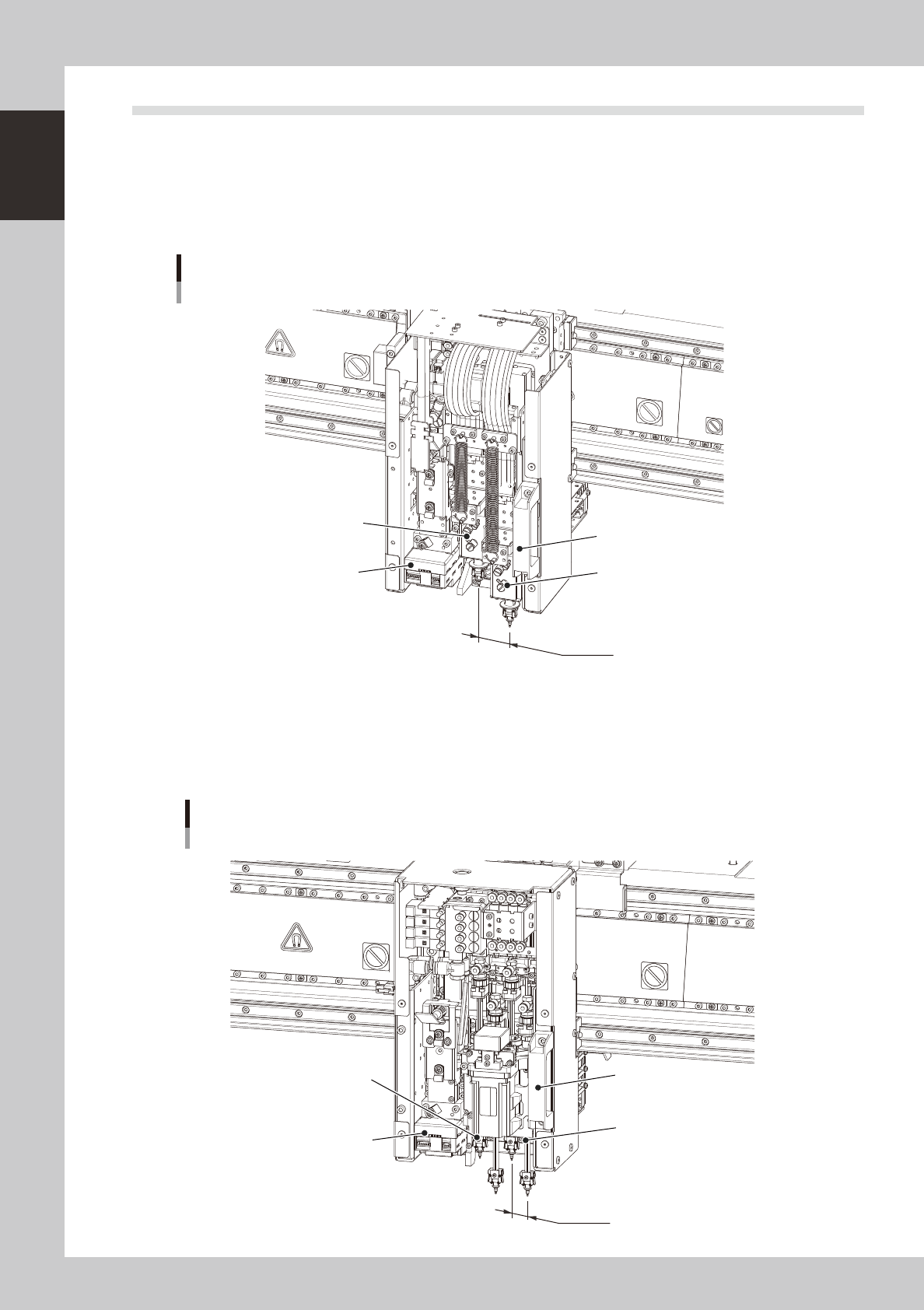
4.1.1 F head
The F head assembly has two pick & place heads and is mounted for each table, which are capable of load
control. On both tables, the left head is designated Head 1 and the right is Head 2, as viewed from the front of
the machine. The spacing between each head is 36mm which is identical with the nozzle pitch of the wafer
tray changer.
Head 2
36mm
Head 1
Head slide handle
Fiducial camera
F head (load control)
Example of A-table
23114-H0-00
4.1.2 4M head
The 4M head assembly has 4 in-line heads and is mounted for each table. On both tables, head numbers are
designated from 1 to 4, from the left as viewed from the front of the machine. The spacing of adjacent nozzles
attached to the head assembly is 18mm.
Head 4
18mm
Head 1
Head slide handle
Fiducial camera
4M head
Example of A-table
23114-H0-00
1-11
1
Part names and functions
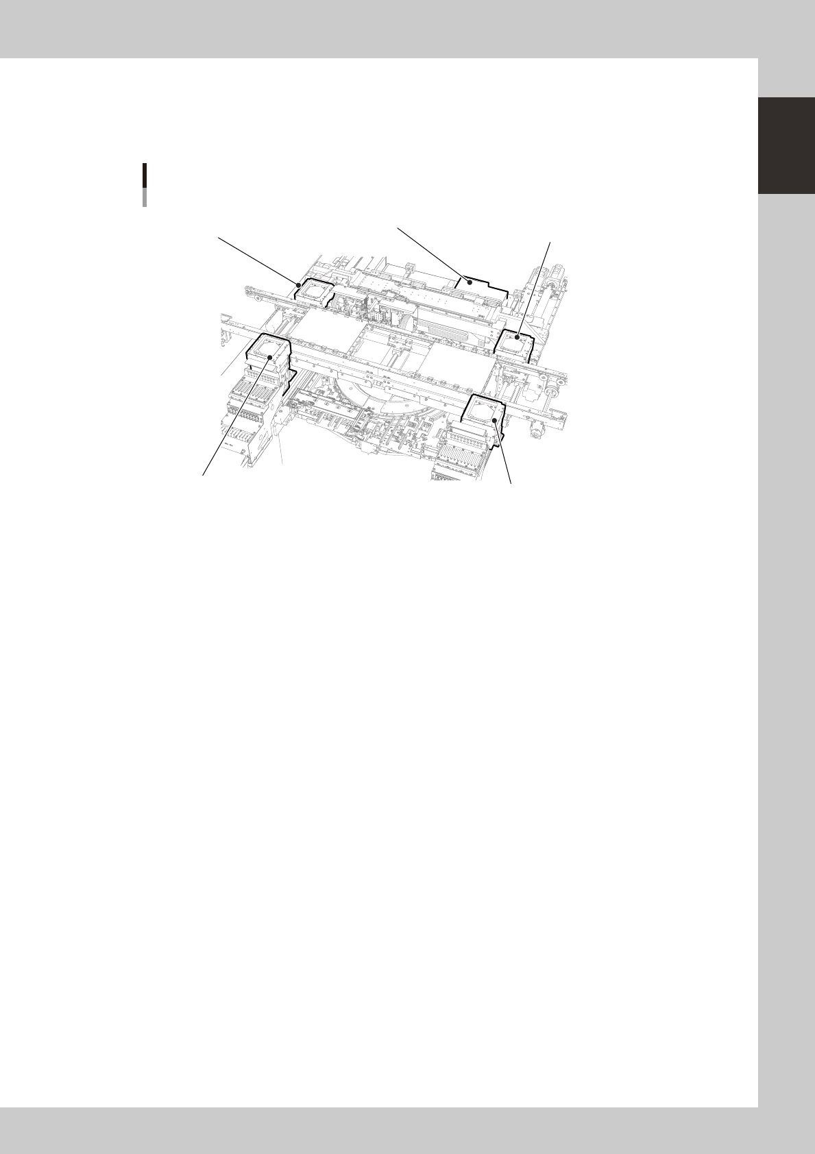
4.1.3 Component recognition cameras
The YSH20 has one component recognition camera (multi-vision camera) on either the front or rear of each
stage. An optional multi-vision camera or single-vision camera can be added. When a wafer tray changer is
used, a wafer camera is installed on the rear side.
B-table
Multi-vision camera or single-vision camera
A-table
Multi-vision camera or single-vision camera
Component recognition cameras
B-table
Multi-vision camera or single-vision camera
A-table
Multi-vision camera or single-vision camera
Wafer camera
23115-H0-00
1-12
1
Part names and functions
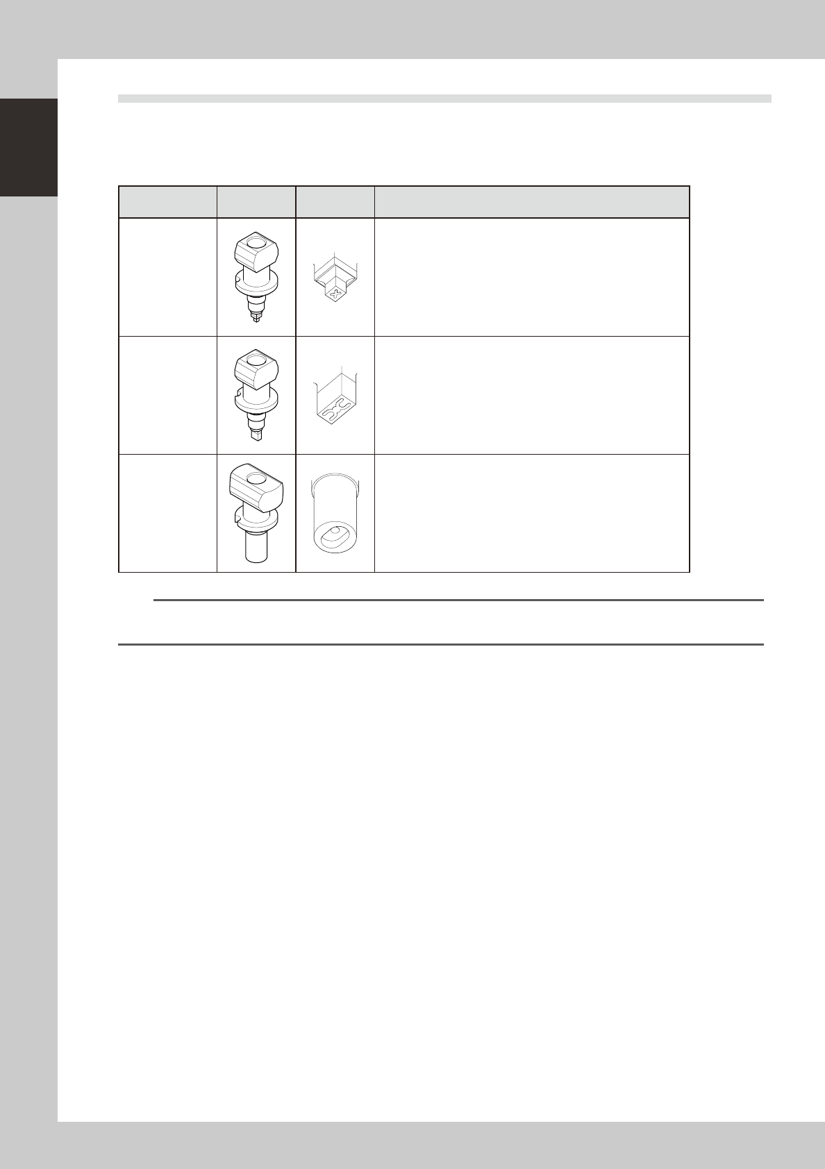
4.2 Nozzle types
To ensure stable component pickup, the correct nozzle that matches the component must be used.
Nozzles that can be attached to each head are described below.
4.2.1 Nozzles for F head
Nozzle type
External
view
Tip shape Suitable components
Type401
0603 to 1005 size chip components, mini-mold transistors
Type402
1608 to 3216 size components, mini-transistors
Type403
4532 to 7343 size components, SOP 10 to 20mm, 5×5mm to
16×16 mm QFP
n
NOTE
For detailed information on suitable component types and size, refer to the specification sheet that came with the
machine. Nozzles other than the above may be available as custom nozzles.