YSH20_Ope_E.pdf - 第49页
1-13 1 Part names and functions 4.3 Nozzle station (option) T he nozzle station accommodates various nozzles for automatic change. T he drawings below sho w the nozzle station No. and the allotted head No. and mating noz…
1-12
1
Part names and functions
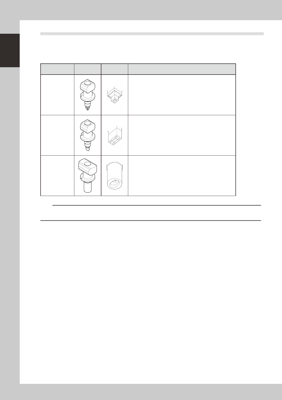
4.2 Nozzle types
To ensure stable component pickup, the correct nozzle that matches the component must be used.
Nozzles that can be attached to each head are described below.
4.2.1 Nozzles for F head
Nozzle type
External
view
Tip shape Suitable components
Type401
0603 to 1005 size chip components, mini-mold transistors
Type402
1608 to 3216 size components, mini-transistors
Type403
4532 to 7343 size components, SOP 10 to 20mm, 5×5mm to
16×16 mm QFP
n
NOTE
For detailed information on suitable component types and size, refer to the specification sheet that came with the
machine. Nozzles other than the above may be available as custom nozzles.
1-13
1
Part names and functions
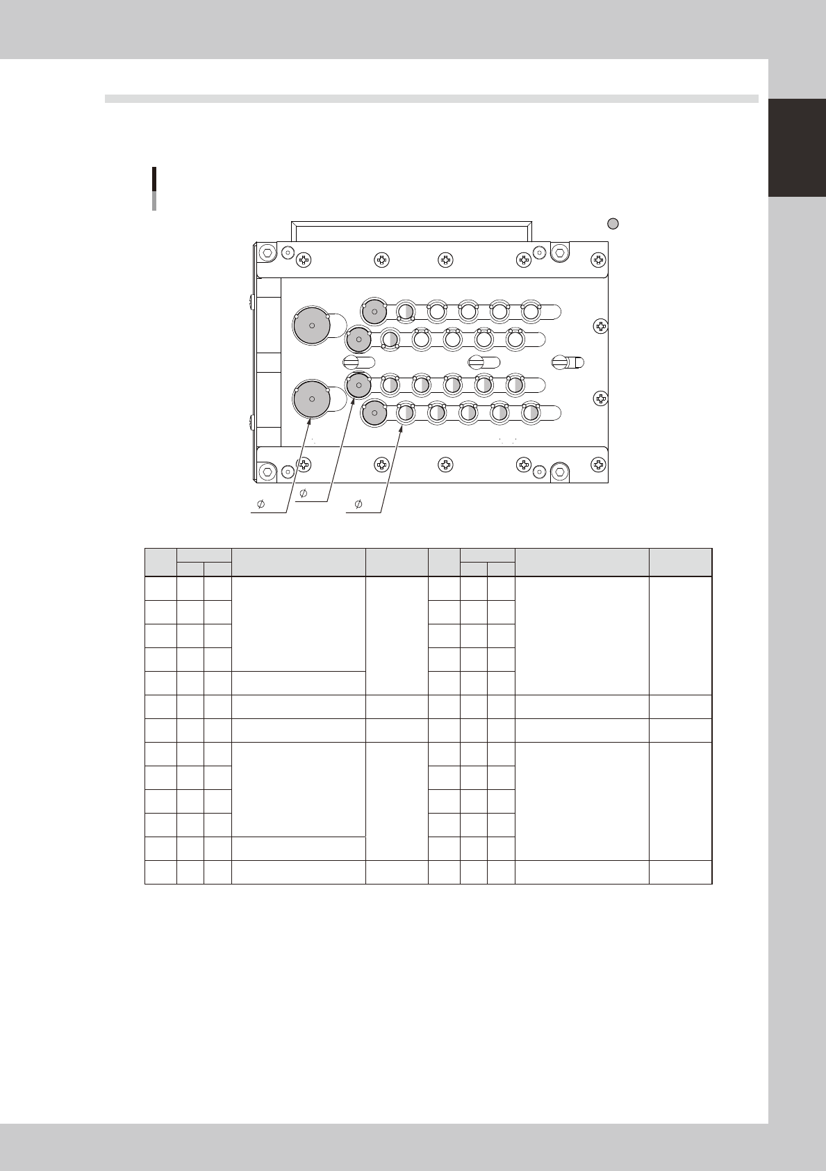
4.3 Nozzle station (option)
The nozzle station accommodates various nozzles for automatic change.
The drawings below show the nozzle station No. and the allotted head No. and mating nozzle type.
123456
7
8
9
101112
1415161718
20
2122232425
13
19
26
Nozzle station
Common to both tables
Custom nozzle pockets
Front of machine
15
10
6
23116-H0-00
No.
Head
Nozzle type
Tip
diameter
No.
Head
Nozzle type
Tip
diameter
FF 4M FF 4M
1 2 4
TYPE401
φ
6
14 - -
TYPE403 or custom nozzle
φ
6
2 1 3 15 - -
3 2 2 16 - -
4 1 1 17 - -
5 - - TYPE403 or custom nozzle 18 - -
6 - - Custom nozzle
φ
10 19 - - Custom nozzle
φ
10
7 1 - Custom nozzle
φ
15 20 2 - Custom nozzle
φ
15
8 2 4
TYPE402
φ
6
21 - -
TYPE403 or custom nozzle
φ
6
9 1 3 22 - -
10 2 2 23 - -
11 1 1 24 - -
12 - - TYPE403 or custom nozzle 25 - -
13 - - Custom nozzle
φ
10 26 - - Custom nozzle
φ
10
1-14
1
Part names and functions
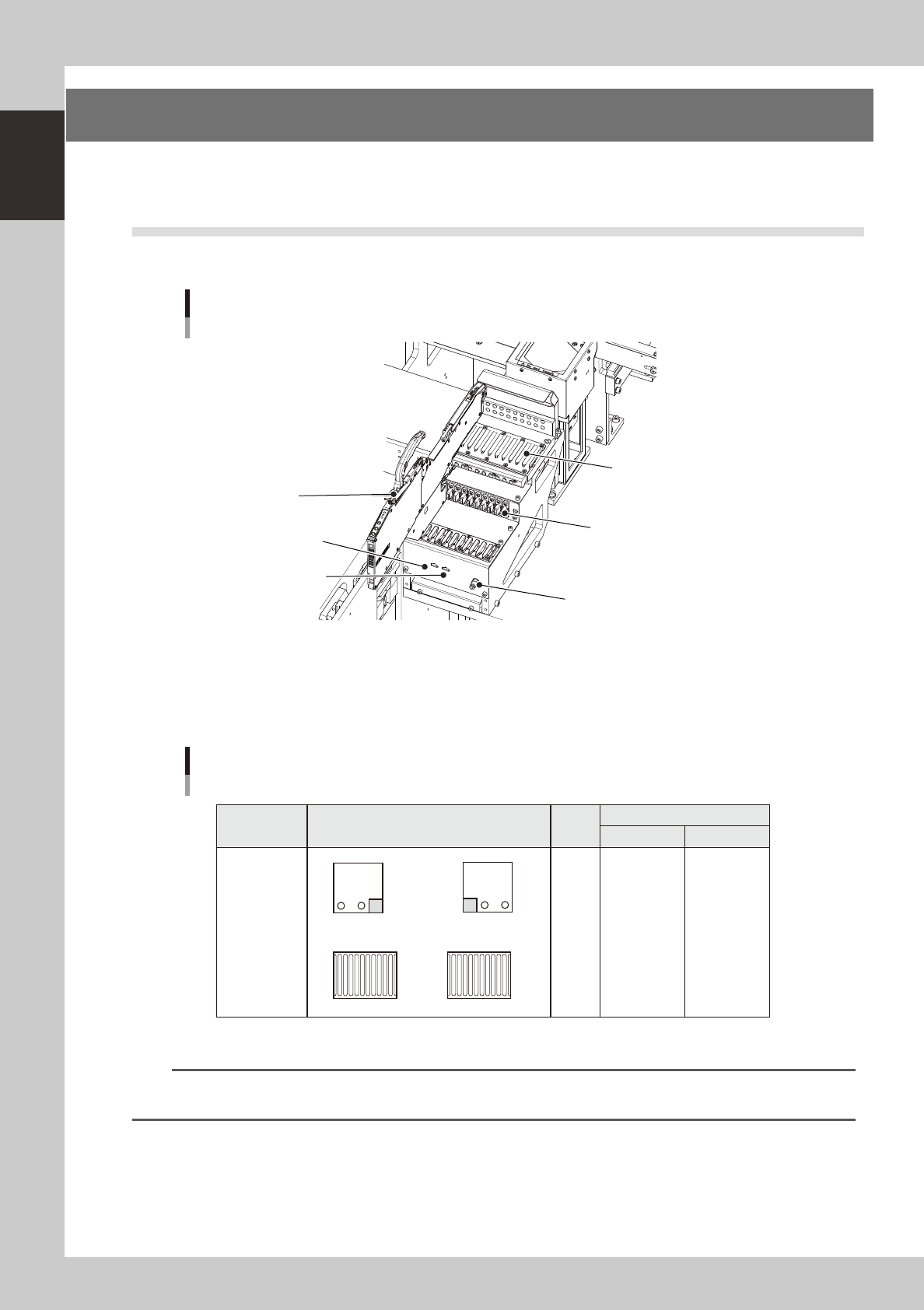
5. Component supply section
The feeder setup section is equipped with feeder plates for installing feeders such as tape feeders, and
power supply connectors and air connectors for driving optional units.
5.1 Supplying components from feeder plates
Tape feeders are installed on the feeder plates and operate by electric power supplied from this machine.
Feeder section
Power connector
DUMP connector
Air connector
Feeder plate (10-feeder plate)
Power/signal connector
SS feeder
23117-H0-00
Head No. and feeder set No.
All feeders can be reached by both heads on each table. Feeder set numbers that can be accessed each head of the
machine are shown below.
B
A
1 2
1 2
Feeder plate layout
Fixed 10-feeder plate
1 to 10
1 to 10
Feeder set No.
Layout
Head
No.
Type
B-table A-table
Fixed 10-feeder
plate
1
2
101 to 110
101 to 110
1
10
101
110
23118-H0-00
n
NOTE
Accessible feeder positions may differ from the above when the Feeder Definition parameter in component
information is set to "Teach" or "Relative".