YSH20_Ope_E.pdf - 第51页
1-15 1 Part names and functions 5.2 Supplying components from a wafer tray changer When supplying components from a wafer tr ay c hanger , set it up as described below . T here are two methods for setting the wafer magaz…
1-14
1
Part names and functions
5. Component supply section
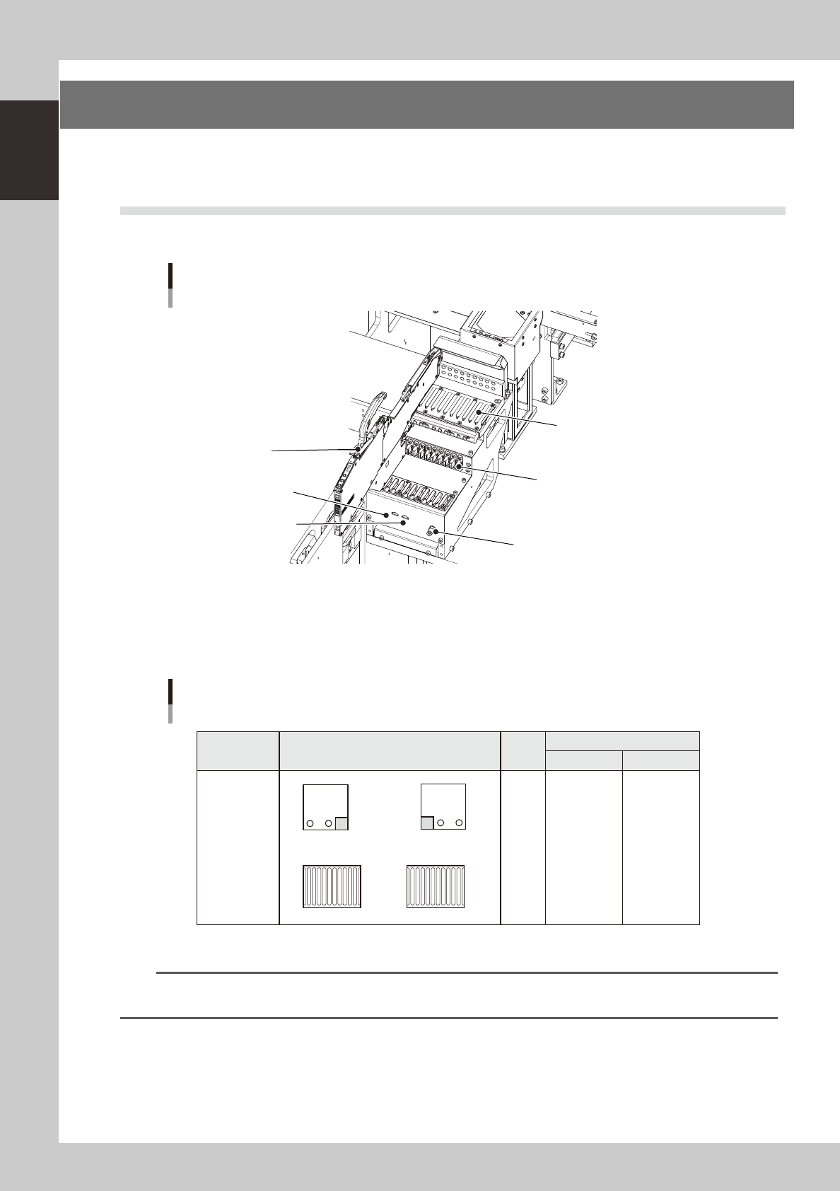
The feeder setup section is equipped with feeder plates for installing feeders such as tape feeders, and
power supply connectors and air connectors for driving optional units.
5.1 Supplying components from feeder plates
Tape feeders are installed on the feeder plates and operate by electric power supplied from this machine.
Feeder section
Power connector
DUMP connector
Air connector
Feeder plate (10-feeder plate)
Power/signal connector
SS feeder
23117-H0-00
Head No. and feeder set No.
All feeders can be reached by both heads on each table. Feeder set numbers that can be accessed each head of the
machine are shown below.
B
A
1 2
1 2
Feeder plate layout
Fixed 10-feeder plate
1 to 10
1 to 10
Feeder set No.
Layout
Head
No.
Type
B-table A-table
Fixed 10-feeder
plate
1
2
101 to 110
101 to 110
1
10
101
110
23118-H0-00
n
NOTE
Accessible feeder positions may differ from the above when the Feeder Definition parameter in component
information is set to "Teach" or "Relative".
1-15
1
Part names and functions
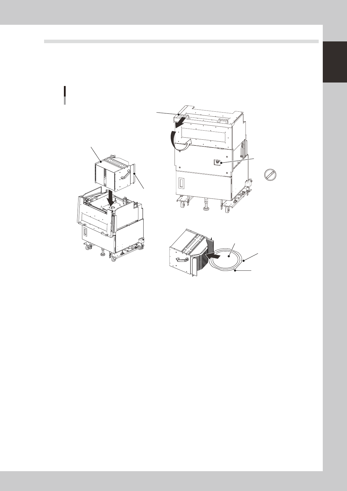
5.2 Supplying components from a wafer tray changer
When supplying components from a wafer tray changer, set it up as described below.
There are two methods for setting the wafer magazine.
• Insert a wafer component (dicing frame) directly into the magazine.
• Insert a wafer component set on a wafer pallet into the magazine.
A
U
T
O
S
E
T
U
P
Wafer tray changer
Component setup
Magazine position
selector switch
Magazine
Stopper
Cover open/close handle
N Setting the magazine
N Setting a wafer component
Notch
Flat side
Wafer component
23119-H0-00
n
Setting a 12-inch wafer component
1
Move the magazine to the wafer exchange position.
Set the magazine position selector switch to "SET UP".
e
2
Open the safety cover.
Press the emergency stop button and open the safety cover on this machine. Then pull the cover open/
close handle toward you to open the cover on the magazine side.
3
Set a wafer component as shown in the above figure.
4
Set the magazine.
Open the stoppers and set the magazine into the machine with the stoppers facing the machine.
5
Close the covers.
Close the covers on the magazine side and on the machine, then cancel emergency stop.
6
Return the machine to operation ready status.
Set the magazine position selector switch to "AUTO". The magazine will move to the operating position.
1-16
1
Part names and functions
n
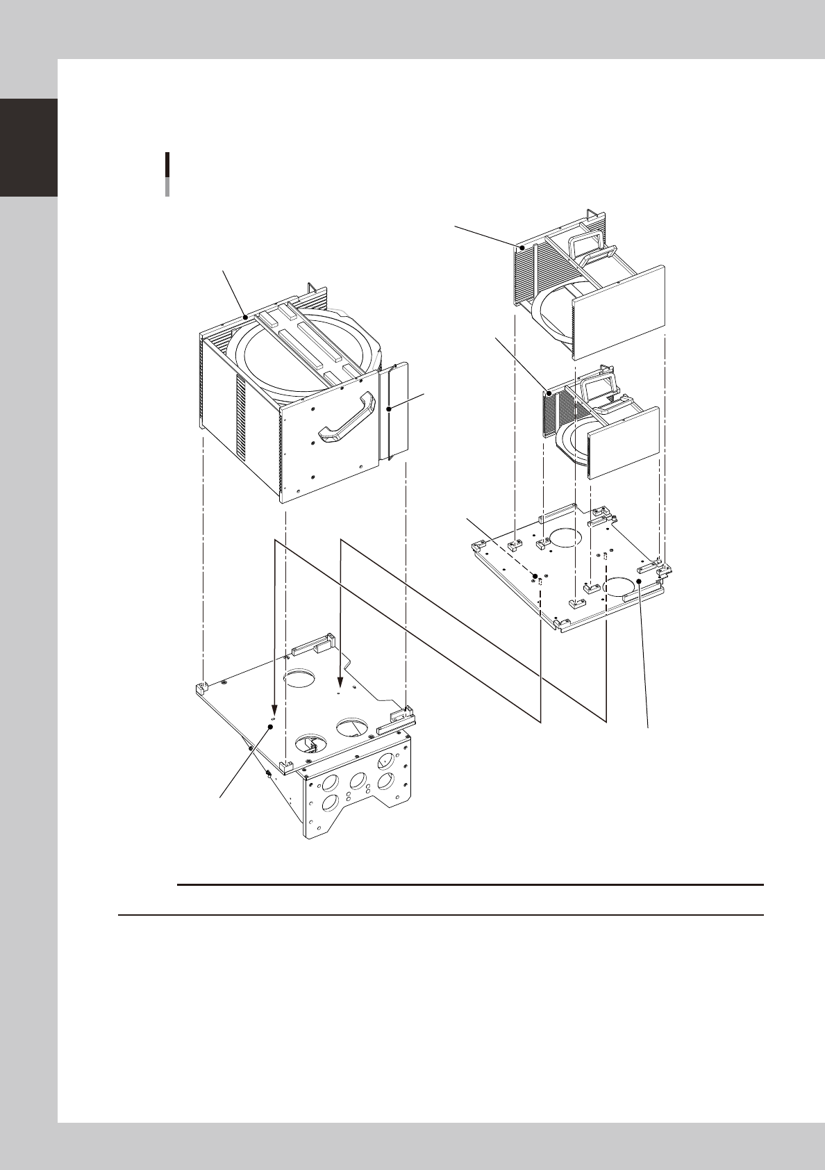
When using wafer components other than 12 inch wafers
When using 6-inch or 8-inch wafers or wafer pallet components other than 12-inch wafer components, use the magazine
size attachment as shown below.
Wafer tray changer
Magazine set position
12-inch wafer magazine
Stopper
8-inch wafer magazine
6-inch wafer magazine
Knock pin
Magazine size attachment
Knock pin hole
23120-H0-00
c