00195655-04_SM_X-Series_FSE_en.pdf - 第20页
Overview of the Modules Serial Number of Module 20 Ser vice Manual (internal ver sion) SIPLACE HF and X Series 2.1 2 . 1 S e r ia l N u m b e r o f M o d u le Serial Number of Module The serial number of you r placement …
Overview of the Modules
Service Manual (internal version) SIPLACE HF and X Series 19
2
2 Overview of the Modules
Overview of the Modules
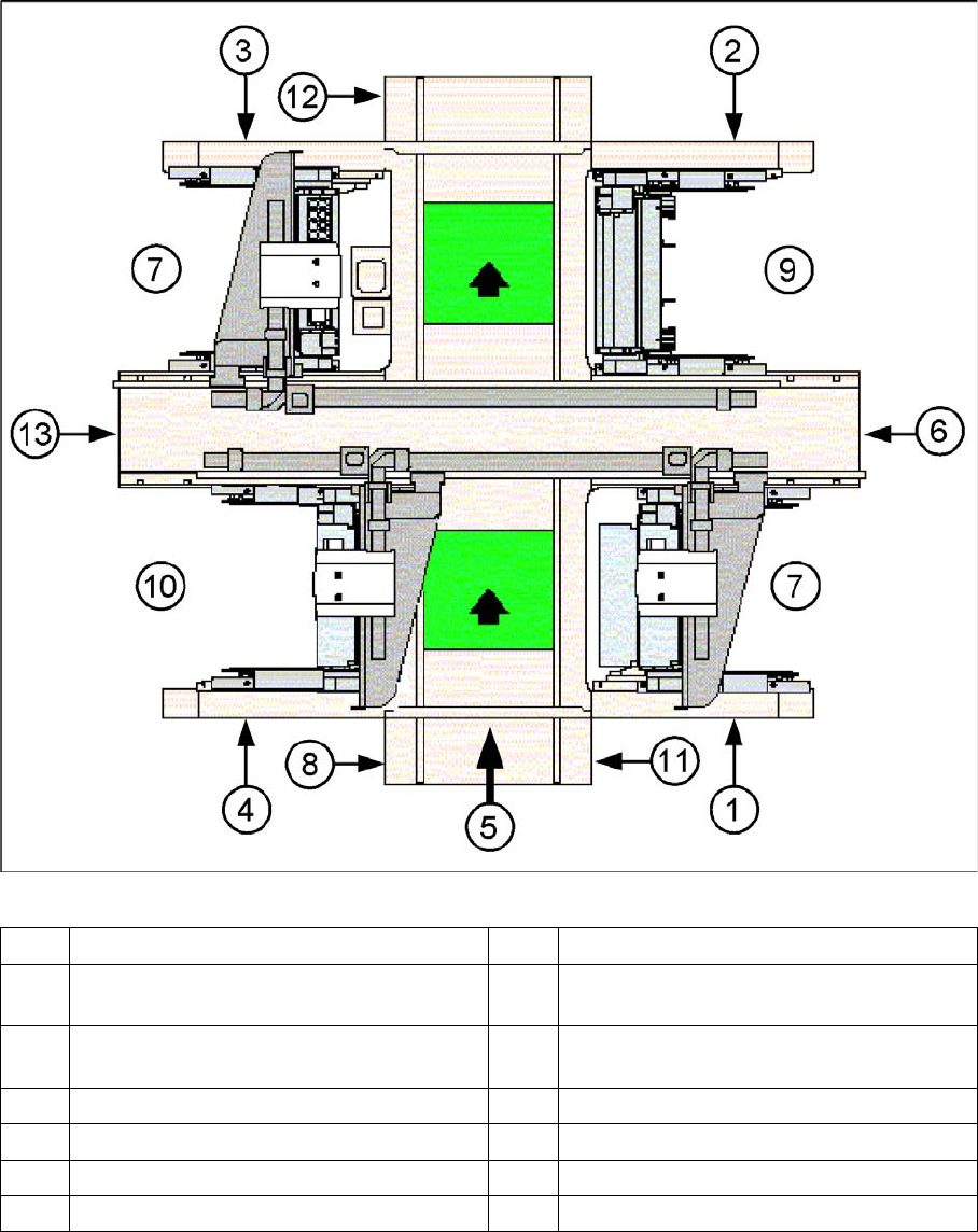
SIPLACE X3 - top view
1 Sector 1 8 Computer unit
2 Sector 2 (main distributor) 9 Location for changeover table or MTC2 for
PA 2
3 Sector 3 10 Location for changeover table or MTC2, by
X2 only
4 Sector 4 (subdistributor) 11 Axis unit placement area 1 (PA1)
5 Transport direction 12 Axis unit placement area 2 (PA2)
6 Pneumatic unit and conveyor control 13 Power supply unit
7 Location for changeover table
Overview of the Modules
Serial Number of Module
20 Service Manual (internal version) SIPLACE HF and X Series
2.1
2.1 Serial Number of Module
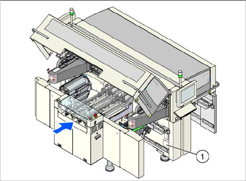
Serial Number of Module
The serial number of your placement machine can be
found on the typeplate. This is located on the inside of lo
-
cation 1, at the side (1).
Service Work
3.2.1 Fitting the One-Piece Covers for the X-Series Measuring Equipment and Tools
Service Manual (internal version) SIPLACE HF and X Series 21
3
3 Service Work
Service Work
3.1
3.1 Measuring Equipment and Tools
Measuring Equipment and Tools
For more information about the measuring equipment and tools used, refer to the service section of our
homepage at www.siplace.com.
3.2
3.2 Basic Machine
Basic Machine
3.2.1
3.2.1 Fitting the One-Piece Covers for the X-Series
Fitting the One-Piece Covers for the X-Series
► Remove all foil from the inside of the protective covers.
► Remove one screw per Schmersal switch on the rucksack and press this downwards.
This is necessary in order to avoid potential problems when fitting the covers.
► Fit two gas pressure absorbers per protective cover.
► Fix the protective covers to the machine with bolts.
Aligning and fastening the covers:
► Loosen 2x screws on the hinge of each cover and place a circlip underneath.
► Roughly align the cover with an angle bracket.
► Now align the covers precisely in relation to the rucksacks (right/left) and the contact points on the
substructure.
► Fix the cover hinges into place with the plate and 2 screws (side fixtures).
► Position the gas pressure absorbers onto the cover wings and secure these with the locking springs.
► Fit the ESD discharge strap for the cover with a screw (DIN7984 M8x12), a circlip and a plate to the
cover wings.
► Check the cover for correct functionality.
Setting the Schmersal switch:
► Refit the screw which fastens the Schmersal switch and was removed to take off the cover.
► Loosen the lower screws fastening the Schmersal switch and adjust these so that they are approx.
1 mm from the cover and positioned centrally to the cover plug.
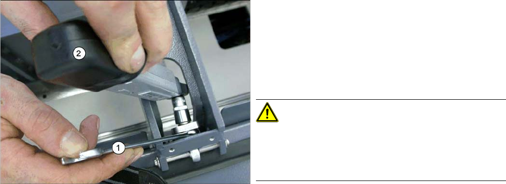
► After alignment, align the hinge so that it is straight
and secure the fixture nuts with Loctite 241.
► Now tighten the nuts with a torque of 6 Nm. To do
this, place a fork wrench (1) over the inner nut and
hold this tight. Then tighten the outer nut with the
torque wrench (2) until the required torque is reached
(wrench will click).
CAUTION!
Do not tighten any more, otherwise you will set a different
torque!
If the covers are removed, use new nuts afterwards, to
prevent any damage.