00195655-04_SM_X-Series_FSE_en.pdf - 第31页
Service Work 3.3.1 Replacing the Trailing Cable Gantries Service Manual (internal ver sion) SIPLACE HF and X Series 31 3.3.1.6 3 . 3 . 1 . 6 R e p la c in g t h e T r a ilin g C a b le f o r X S e r ie s M a c h in e s u…
Service Work
Gantries 3.3.1 Replacing the Trailing Cable
30 Service Manual (internal version) SIPLACE HF and X Series
Conversion for SIPLACE HF up to A 219
These versions of the trailing cable can also be used with SIPLACE HF machines up to machine number
A-219, in conjunction with the "Trailing cable retrofit kit" 03046248-01.
▪ Trailing cable for HF machines with one gantry
– [03039706S01] Trailing cable analog 1P
▪ Trailing cable for HF machines with two gantries in uneven locations (1 and 3)
– [03039708S01] Trailing cable analog 2P U
▪ Trailing cable for HF machines with two gantries in even locations (2 and 4)
– [03039709S01] Trailing cable analog 2P G
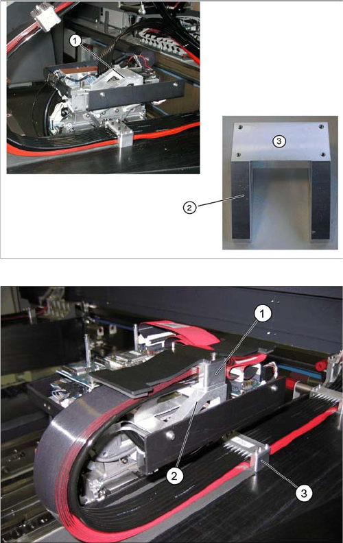
The difference lies in the fact that the new pressure plate
can no longer be fastened to the existing cable support.
The old cable support (1) therefore needs to be replaced
with a new one.
► Replace the old cable support (1) with the new cable
support (2) from the retrofit kit. The new cable sup
-
port has four drilled holes (3) for fastening the new
pressure plate.
► Fit the pressure plate for the new trailing cable onto
the new cable support, with the four M3x35 screws
from the retrofit kit.
► If the pressure plate on the gantry does not fit into the
existing holes drilled, loosen the clamp on the pres
-
sure plate and shift it accordingly.
► Tighten the clamp again and fit the pressure plate at
the correct position of the gantry drillings.
Service Work
3.3.1 Replacing the Trailing Cable Gantries
Service Manual (internal version) SIPLACE HF and X Series 31
3.3.1.6
3.3.1.6 Replacing the Trailing Cable for X Series Machines up to B-078 [03003199-xx]
Replacing the Trailing Cable for X Series Machines up to B-078 [03003199-xx]
Parts
▪ Trailing cable, digital 1P [03015419-03]
▪ Trailing cable, digital 2P U [03002306-03]
▪ Trailing cable, digital 2P G [03003199-03]
▪ Hose pliers for cutting the pneumatic hose
▪ Pipe/hose cutters [00381443-xx]
▪ Hose unlocking tool [03047090-xx]
▪ Sealing varnish Loctite 241 [02101037-xx]
Preparation
The trailing cable is supplied as a complete assembly. In accordance with your machine's configuration,
you will need to remove the relevant modules, covers and cover plates before you can dismantle the
trailing cable.
► Where necessary, remove the cover plates from the gantry trailing cable. Mark their exact position
to ensure correct replacement later.
► Remove the top central cover from the SIPLACE machine.
► Remove the upright covers over the trailing interface gantry, so that you can reach the trailing cable.
Overview
CAUTION!
Some of the machines up to number B-078 have been
converted to accommodate the new trailing cable from
number B-079. Before ordering the trailing cable, please
compare the item numbers on your current machine. The
conversion of a customer machine involves significant
costs and is only possible at the SIPLACE headquarters.
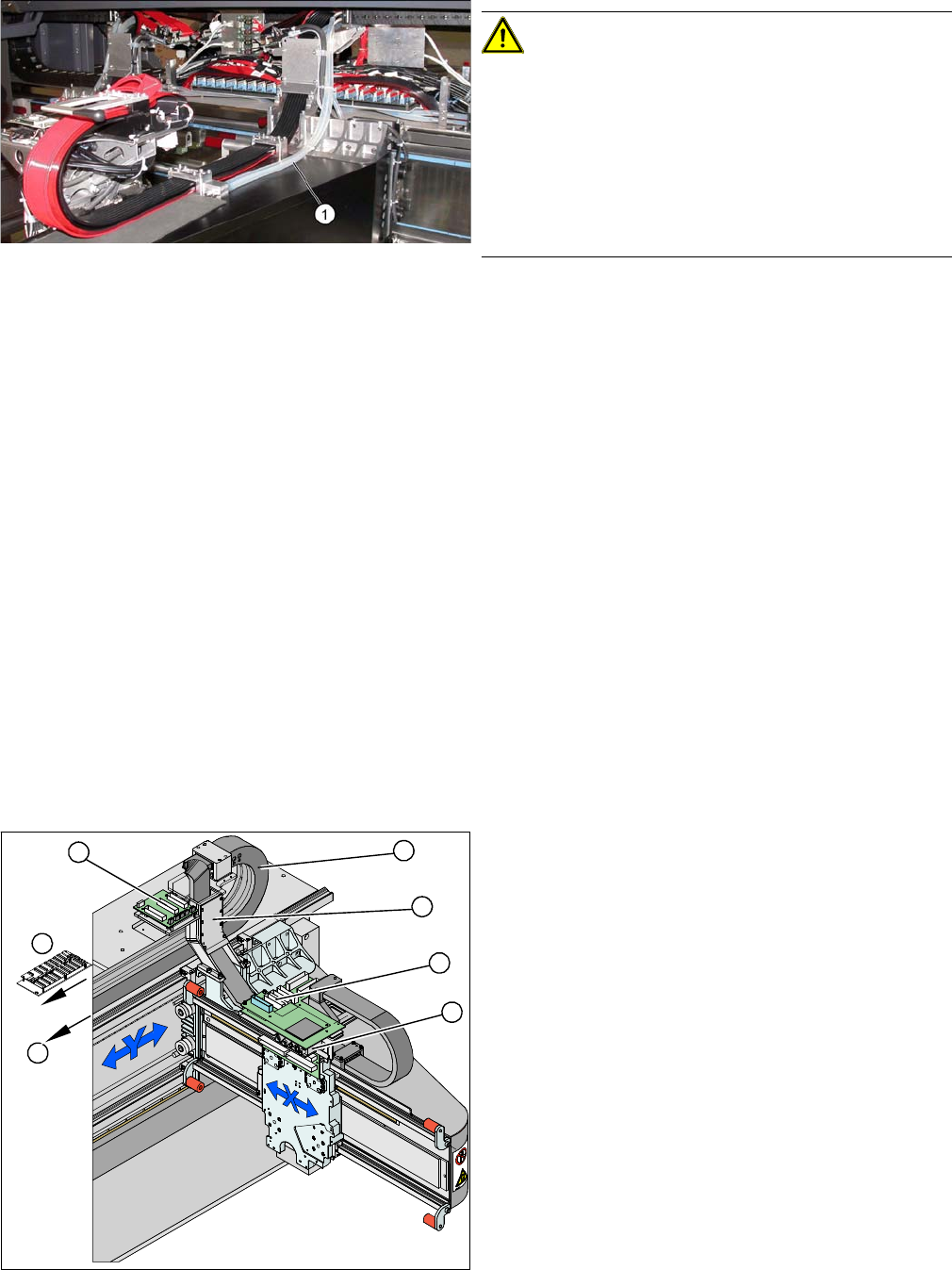
If the trailing cable has the additional white hoses (1), this
is a new trailing cable.
► The flat ribbon cable and the camera cable are run
from the head board (1) via the trailing cable console
(2) and the power track chain (3) to the gantry inter
-
face (7) and the trailing cable interface gantry (4).
The camera cable ends at the hotlink board (8).
► The pneumatic hoses are fed from the pneumatic
distributor (6), via the trailing cable console (2) and
the power track chain (3) to the gantry distributor (5) .
5
5
6
7
1
4
3
2
Service Work
Gantries 3.3.1 Replacing the Trailing Cable
32 Service Manual (internal version) SIPLACE HF and X Series
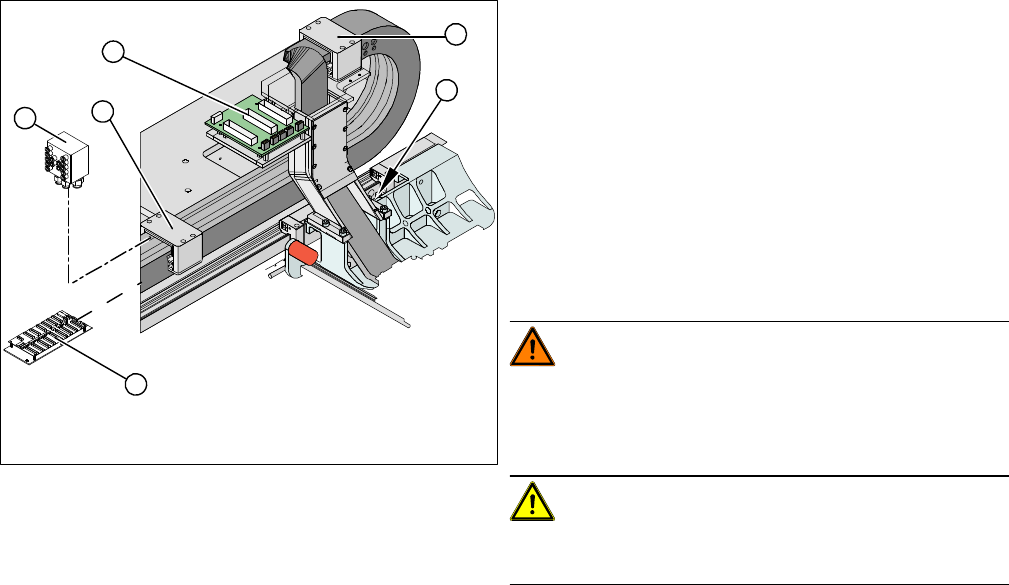
Removal
► Loosen the flat ribbon cable and the camera cable at
the trailing cable interface (1) or the hotlink board.
When opening the flat ribbon cable, take care not to
lose the brackets for the press-fit connections. They
could fall out and be lost.
► Remove cable ties where necessary.
► Remove the cover on the gantry distributor (5).
► Loosen the screws fastening the gantry distributor
(5).
► Remove all the pneumatic hoses from the pneumatic
distributor (2).
WARNING!
Risk of injury to hands
Use the hose unlocking tool to remove the hoses
[03047090-xx].
CAUTION!
Note the order in which the terminal connections are ar
-
ranged. You will need this for subsequent reconnection.
3
3
4
5
1
2