00195655-04_SM_X-Series_FSE_en.pdf - 第48页
Service Work Gantries 3.3.3 Replacing Gantries 48 Ser vice Manual (internal ver sion) SIPLACE HF and X Series Dismantling the Magnet Cover and the Magnetic Strip ► Remove the long magnetic strip (4) . ► Close the magnet …
Service Work
3.3.3 Replacing Gantries Gantries
Service Manual (internal version) SIPLACE HF and X Series 47
3.3.3
3.3.3 Replacing Gantries
Replacing Gantries
Overview of gantry versions
▪ SIPLACE HF to Ma. No. A219: [03020302Sxx]
▪ SIPLACE HF from Ma. No. A220: [03025822Sxx]
▪ SIPLACE X-Series to Ma, No. B078: [03025822Sxx]
▪ SIPLACE X-Series from Ma. No. B079: [03039725-xx]
▪ SIPLACE D3, SIPLACE X4i gantry 2+4: [03039725-xx]
▪ SIPLACE X4I gantry 1+3: [03027255-xx]
Preparation
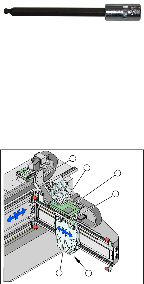
► Dismantle the placement head.
► Remove the head adapter board (3). The X mount fixtures (2) are now accessible.
► Unplug the following cables from the head board (5) and remove them from the X mount (2):
▪ X motor cable
▪ The Y axis incremental encoder
▪ Temperature sensor (if supplied).
Tools and equipment
▪ Blue covers [00355787-xx]
▪ Torque wrench [00376625-xx]
▪ Set of socket wrenches [00376516-xx]
▪ Hexagonal ball-head insert ¼" size 5 100 mm
[00386341-xx]
see adjacent photo.
Depending upon the configuration of the machine, you
will need to remove the relevant assemblies, covers and
cover plates before you can dismantle the gantry.
1. X drive (primary) with head mount
2. X mount with trailing cable
3. Head adapter board
4. Mount with PCB camera
5. Head board
6. Trailing cable console
5
5
6
1 4
3
2
Service Work
Gantries 3.3.3 Replacing Gantries
48 Service Manual (internal version) SIPLACE HF and X Series
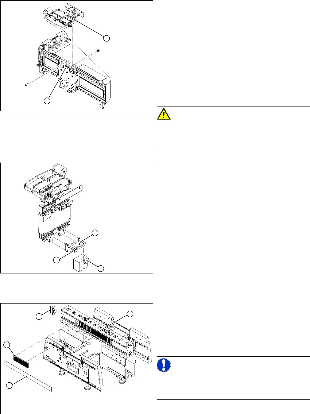
Dismantling the Magnet Cover and the Magnetic Strip
► Remove the long magnetic strip (4).
► Close the magnet cover plate and fix it to the machine base.
► Unplug the proximity switch cable (2) and pull it for
-
wards, out of the head mount.
► Undo the 8 screws (4 x at front/ 4x at back) fastening
the X mount (1) and pull these up and out, together
with the trailing cable.
► Loosen the two trailing cable pressure plates on the
X gantry.
► Remove the trailing cable as far as the trailing cable
console (see "3.3.1.7 Replacing the Trailing Cable
(IGUS) for D3/X4I/X Series from B-079 [03021065-
xx]" [ ➙ 36]).
► Fasten the X mount at a suitable point.
CAUTION!
Make sure that the flat ribbon cable and the pneumatic
hoses are not rubbed against any parts or folded. Look
out for sharp edges.
► Undo the 4 screws fastening the PCB camera mount
(1). Remove the complete unit, including PCB cam
-
era (3) and damping bracket (2).
► Remove the connection cable fixtures from the gan
-
try.
► For strain-relief purposes, fix the mount (1) to a suit
-
able place. Take care not to damage the camera.
2
1
1
3
2
► Lift the magnet cover plate (1) at the side with the
long magnetic strip and then fix the end of the cover
plate to the X gantry with adhesive tape. You can now
access the long magnetic strip.
► Lever up the blue covers and loosen the 16 screws
fastening the long magnetic strip (4).
NOTICE!
If the blue cover is damaged (kinks, cracks etc.), replace
it during reinstallation. White or pale patches in the plastic
indicate areas of damage.
1
4
3
2
Service Work
3.3.3 Replacing Gantries Gantries
Service Manual (internal version) SIPLACE HF and X Series 49
► Remove the bumper (3) from the side with the long magnetic strip (4).
► Push the gantry over the magnet cover plate and out of the magnetic strip's area of influence.
Removal
► Enlist the help of a second strong person.
► Stand firmly next to the gantry and hold it with both hands, while the other person removes the re
-
maining two screws.
► Lift the gantry off the guide trolley and carry it out of the machine.
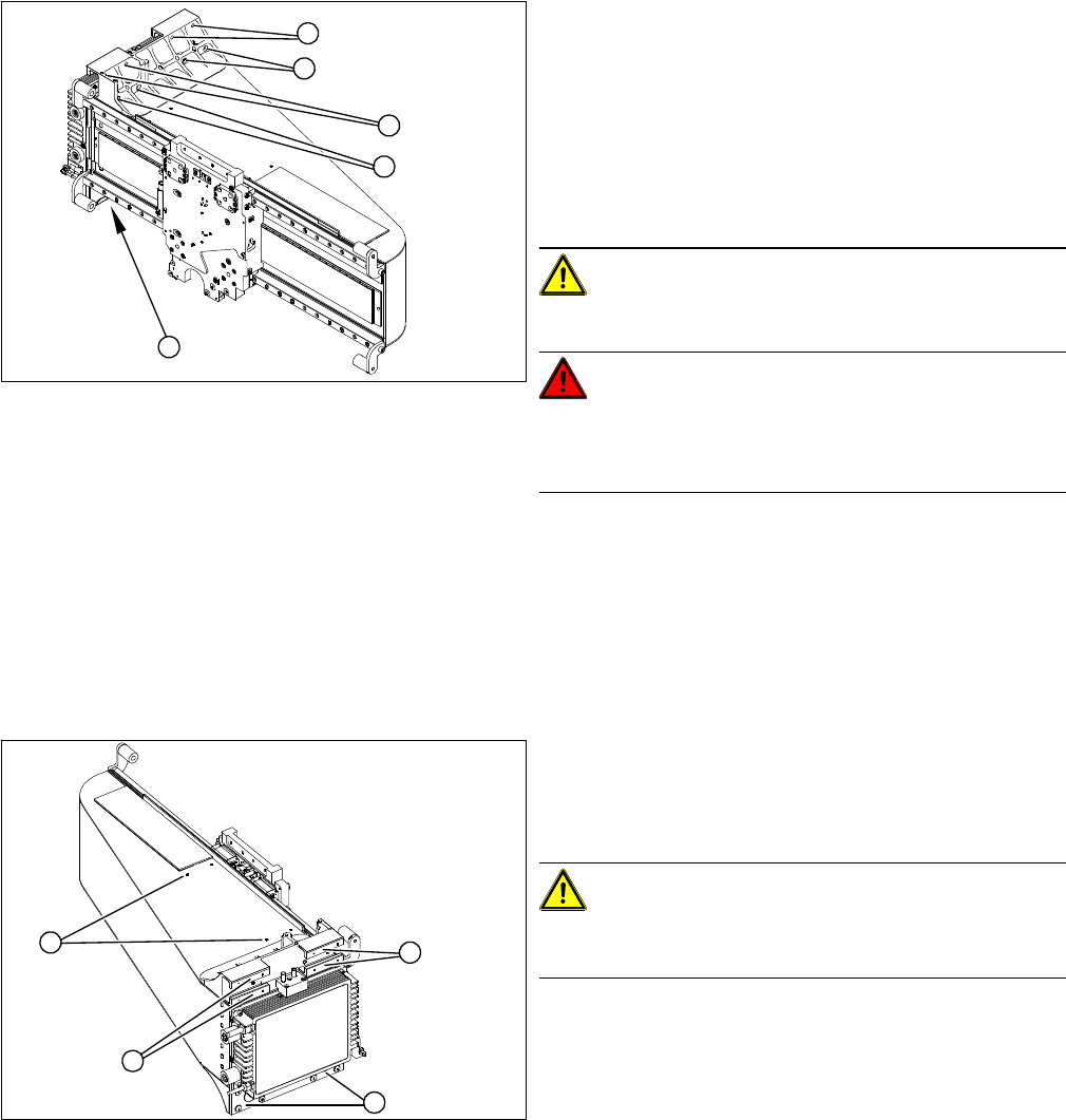
Installation
1. 8 fastening screws at the top (M6 x 14)
2. 8 fastening screws at the bottom (M6 x 22)
► First remove 14 of the 16 screws (6 from the top and
8 from the bottom).
► Please note that the screws are of different lengths.
Mark the positions of each screw. The screws must
be placed back in the same positions after service
work.
CAUTION!
The gantry is heavy (approx. 37 kg).
DANGER!
Please take special care when working in the vicinity of
the powerful magnetic fields produced by the X axis mag
-
netic strip. Risk of serious injuries through trapped limbs.
1
1
1
1
2
► Check whether the holes (4 x M3) for the trailing ca
-
ble pressure plates (1) on the new gantry have been
properly drilled through. If not, re-cut the thread with
an M3 screw tap.
CAUTION!
Take care not to damage the surface of the gantry during
drilling.
► Carefully rub the contact surfaces (2) on the new gan
-
try with a dressing stone (oil stone) and wipe clean
with a cloth and ethanol.
2
2
1
2