00195655-04_SM_X-Series_FSE_en.pdf - 第54页
Service Work Gantries 3.3.5 Replacing the X Drive (Primary) [03039726- xx] 54 Ser vice Manual (internal ver sion) SIPLACE HF and X Series Removal 1. X drive (pri mary) with head mount 2. X mount with trailing cable 3. He…
Service Work
3.3.5 Replacing the X Drive (Primary) [03039726-xx] Gantries
Service Manual (internal version) SIPLACE HF and X Series 53
Installing the scale
► Insert the new scale behind the head plate.
► Attach the new scale exactly to the lay-on edge on the gantry.
► Pull part of the cover strip off the adhesive strip and place the front end of the scale on the marked
position. The scale must be positioned at the lay-on edge.
► Now pull away the cover strip "bit by bit" and firmly fix the scale (to about halfway along the gantry).
► Move the head plate so that you can fix the rest of the scale.
► Press the scale down with a soft, clean cloth.
► Carefully pull off the cover strip.
► Use ethanol to wipe the scale and remove any adhesive residues or dirt.
► Fit the incremental encoder. This procedure is described in Chapter "Replacing the X Axis Incremen
-
tal Encoder".
See also
3.3.6 Replacing the X Axis Incremental Encoder [ ➙ 58]
3.3.5
3.3.5 Replacing the X Drive (Primary) [03039726-xx]
Replacing the X Drive (Primary) [03039726-xx]
Required equipment
▪ Service pack X drive [00377437-xx] for SIPLACE HF/X machines
–X drive
– 4 x dismantling screws
– 8 x lock screws (M4x60)
– Templates for TwinHead and DLM2
– 6 grub screws M4x6-ST
– Plastic thickness gauge 0.4 mm (approx. 50 cm long and 10 cm wide)
– Foam rest 500 mm x 50 mm x 20 mm
▪ Xenon flashlight (non-magnetic)
▪ Torque wrench with socket-head adapter
▪ Loctite 241
CAUTION
Take care when handling the incremental scale.
Do not touch the incremental tracks with bare fingers.
CAUTION
Make sure that no blisters or uneven areas are formed.
If this does occur, the scale must be removed and replaced with a new scale.
NOTICE
Only for HF machines up to machine number A219.
The service pack for the X drive [00375245-01] only fits HF machines up to machine number
A219.
Service Work
Gantries 3.3.5 Replacing the X Drive (Primary) [03039726-xx]
54 Service Manual (internal version) SIPLACE HF and X Series
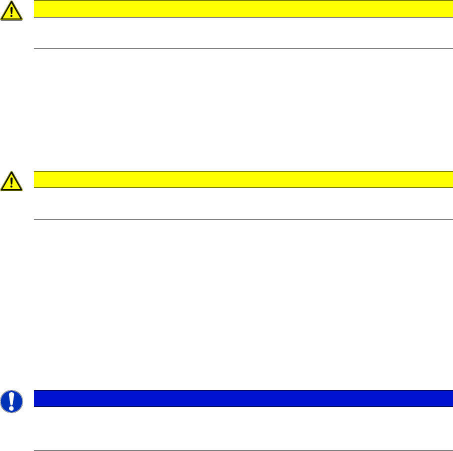
Removal
1. X drive (primary) with head mount
2. X mount with trailing cable
3. Head adapter board
4. Mount with PCB camera
5. Head board
► Dismantle the placement head.
► Remove the head adapter board (3). The X mount fix
-
tures (2) are now accessible.
► Unplug the following cables from the head board (5)
and remove them from the X mount (2):
⇨ X motor cable
⇨ The Y axis incremental encoder
⇨ Temperature sensor
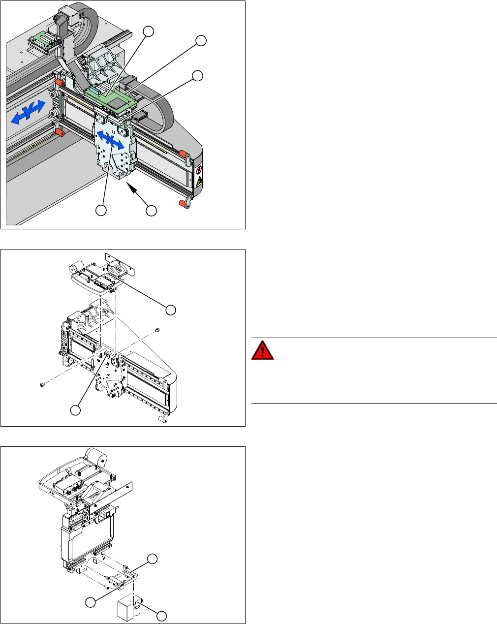
► Unplug the proximity switch cable (2) and pull it for
-
wards, out of the head mount.
► Undo the 8 screws (4 x at front/ 4x at back) fastening
the X mount (1) and pull these up and out, together
with the trailing cable.
► Fasten the X mount at a suitable point.
DANGER!
Make sure that the flat ribbon cable and the pneumatic
hoses are not rubbed against any parts or folded. Look
out for sharp edges.
► Undo the 4 screws fastening the PCB camera mount
(1). Remove the complete unit, including PCB cam
-
era (3) and damping bracket (2).
► Fix the mount (1) to a suitable point on the machine
base. Take care not to damage the camera.
5
5
1 4
3
2
2
1
1
3
2
Service Work
3.3.5 Replacing the X Drive (Primary) [03039726-xx] Gantries
Service Manual (internal version) SIPLACE HF and X Series 55
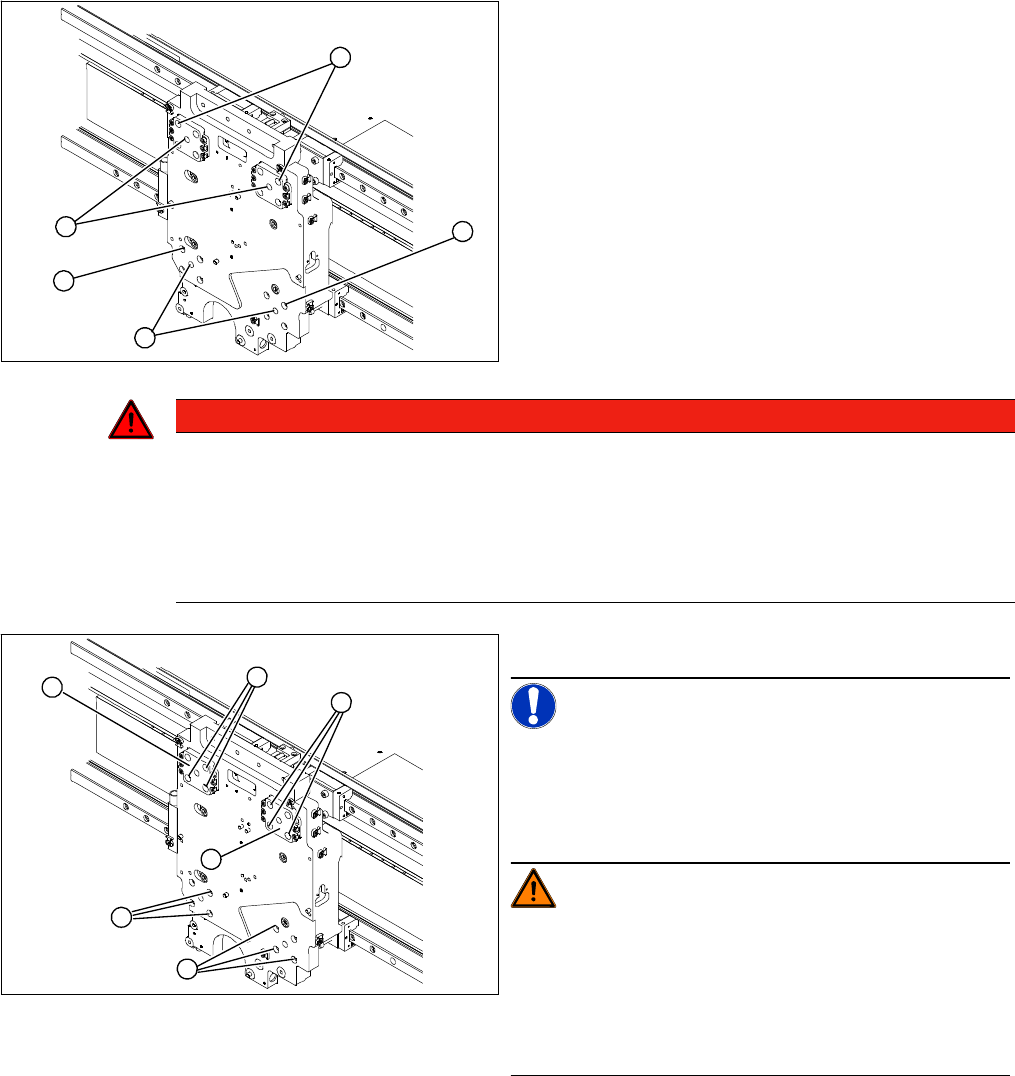
1. Insert 4 x dismantling screws
2. 4 x lock screws M4x60
► On each of the 4 sides, insert 1 dismantling screw (1)
and tighten as far as the stopper.
► Remove one fastening screw (2) from each of the 4
sides.
► Replace this fastening screw with a M4x60 lock
screw in each case. This prevents the motor from fall
-
ing down when pressure is applied to it.
1
2
2
1
2
DANGER
Risk of fatal injuries through trapped limbs.
For safety, place a piece of foam between the X drive and the magnetic strip.
For additional safety, keep the 4 dismantling screws in place until the X drive has been removed
from the machine.
► Once the X drive is out of the vicinity of the strong magnetic field, it can be removed from
the machine. Loosen the 4 lock screws to remove it.
► Undo the remaining 12 fastening screws (1).
NOTICE!
Note the screw lengths!
Make a note of the different screw lengths. These will
need to be correctly replaced later. Mark the positions of
the individual screws.
WARNING!
Do not undo or loosen the screws on the Z axis compen
-
sation (2), which have been secured with locking varnish.
Screw in the dismantling screws in turn, so that the X
drive is evenly pushed away from the magnetic field of
the magnetic strip. The X drive is now held by the 4 lock
screws.
1
1
1
2
2
M4 x 8
M4 x 18
M4 x 14
1