00195655-04_SM_X-Series_FSE_en.pdf - 第63页
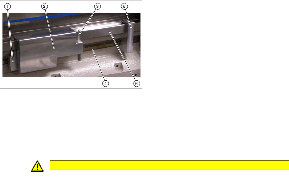
Service Work 3.3.7 Replacing the Y Axis Scale [03005490-xx] Gantries Service Manual (internal ver sion) SIPLACE HF and X Series 63 ► Position the guide device (5) at a suitable distance to the hole on the guide rail (6) …
Service Work
Gantries 3.3.7 Replacing the Y Axis Scale [03005490-xx]
62 Service Manual (internal version) SIPLACE HF and X Series
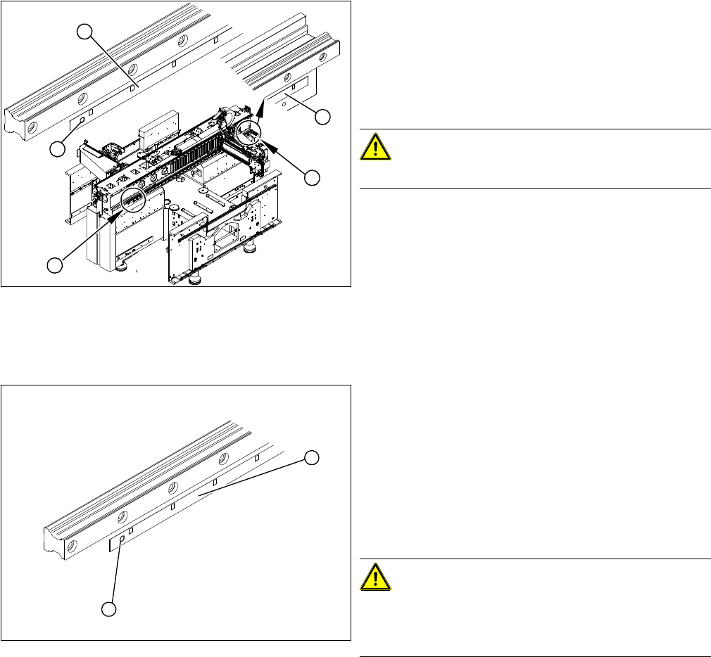
Removal
Installation
► If necessary, remove the side covers on the machine,
for better accessibility (4) .
► Move the gantries into the position which allows you
best access.
► Use the chisel to lever the scale off the right side (1)
of the machine base.
CAUTION!
Make sure that you do not damage the drilling (2).
► Remove the scale (3).
► Use the chisel to remove any adhesive residues from
the contact surface. Wipe the contact surface clean
with a multiflex pad.
► Clean the contact surface with ethanol. The surface
to be fixed down must be clean and free of grease.
1
4
2
3
4
► Move the gantries to the position which gives you
best access to the whole scale.
► Wear protective gloves.
► Attach the adhesive strip to the new scale and then
return this to the packaging.
► Pull the packaging slightly back.
► Pull the transparent cover strip approx. 5 cm off the
adhesive strip on the back of the scale.
CAUTION!
Make sure the scale is not bent or rubbed against any
parts.
Also make sure that it is not scratched!
► Fit the scale (1) so that the pin (2) of the scale slides
into the hole.
1
2
Service Work
3.3.7 Replacing the Y Axis Scale [03005490-xx] Gantries
Service Manual (internal version) SIPLACE HF and X Series 63
► Position the guide device (5) at a suitable distance to the hole on the guide rail (6) and fix with the
screw.
► Pull the transparent cover strip off completely.
► Pull the fixing pin (3) out of the adhesive device (2).
► Place the adhesive device (2) onto the guide rail.
► Insert the fixing pin (3) into the adhesive device (2) so that the scale runs between the guide (1) and
the pin (3).
► Wrap the transparent cover strip from the adhesive strip around the fixing pin.
► Slowly pull off the transparent strip; press down the rollers of the adhesive device and fix the whole
scale as far as possible (up to the gantry).
► Remove the adhesive device and move the gantry so that you can fix the rest of the scale.
► Change the adhesive device and finish fixing the scale completely.
► Press the rest of the scale down with your hand and with the help of a tear-resistant cloth.
► Remove the centering pin from the left side of the scale.
► Clean the scale with a cloth and ethanol.
► Clean the reading surface of the incremental encoder with a cloth and ethanol or with a SIPLACE
cleaning tip [00352931-xx].
► Fit the incremental encoder with the three fastening screws so that there is a gap of 0.4 mm between
the incremental encoder and the scale. Use the corresponding thickness gauge (plastic).
► Check the track signals.
1. Guide with press roller
2. Complete adhesive device
3. Fixing pin
4. Scale
5. Guide device
6. Guide rail
CAUTION
Set the fixing pin correctly
The fixing pin for the scale must be set so that it touches the screw and can guide the scale,
without the latter slipping out.
Service Work
Gantries 3.3.8 Replacing the Y Linear Motor Secondary Part (Magnets)
64 Service Manual (internal version) SIPLACE HF and X Series
3.3.8
3.3.8 Replacing the Y Linear Motor Secondary Part (Magnets)
Replacing the Y Linear Motor Secondary Part (Magnets)
Tools
▪ Rubber mallet
▪ New cover, where necessary [00355787-xx]
▪ Thickness gauge (plastic) 0.4 mm (30 cm long/ 12 cm wide)
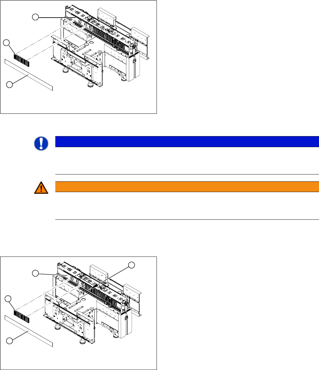
Removal
► Lever up the blue covers.
► Loosen the screws (1) fastening the magnetic strips and remove the individual magnetic strips.
Installation
► Remove the magnetic cover plate (2). You might
need to enlist the help of a second person.
► Lift both sides of the cover plate at the same time.
► Pull it out towards one side, until it reaches the gan
-
try.
► Insert the notch of the shorter end of the cover plate
into the groove between the two magnetic strips (2).
► Move the gantry over this groove, until the cover plate
can be removed.
1
3
2
NOTICE
Damage
If the blue cover is damaged (kinks, cracks etc.), replace it during reinstallation. White or pale
patches in the plastic indicate areas of damage.
WARNING
Risk of serious injuries through trapped limbs.
Please take special care when working in the vicinity of the powerful magnetic fields produced
by the magnetic strip.
► Carefully rub the contact surfaces (1) of the magnet
with a dressing stone (oil stone) and wipe clean with
a cloth and ethanol.
► Fit the magnetic strip (2). Make sure that there is a
gap of 0.8 mm between the individual magnetic
strips.
► Tighten the screws to a torque of 9.5 N.
► Check the blue cover for damage and replace if nec
-
essary.
4
1
3
2