00195655-04_SM_X-Series_FSE_en.pdf - 第68页
Service Work Gantries 3.3.9 Removing the Magnet Cover and Replacing the Magne tic Plates 68 Ser vice Manual (internal ver sion) SIPLACE HF and X Series ► Knock the cover into p lace with a rubber ma llet and block of wo …
Service Work
3.3.9 Removing the Magnet Cover and Replacing the Magnetic Plates Gantries
Service Manual (internal version) SIPLACE HF and X Series 67
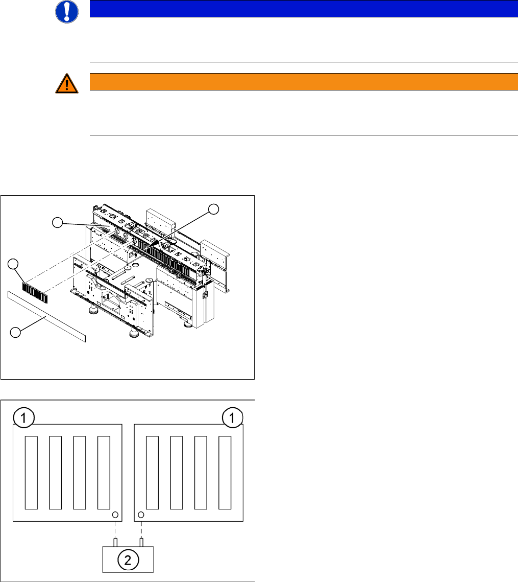
► Lever up the blue covers.
► Unscrew the screws fastening the magnetic plate (2) and remove the plate.
Installation
NOTICE
Damage
If the blue cover is damaged (kinks, cracks etc.), replace it during reinstallation. White or pale
patches in the plastic indicate areas of damage.
WARNING
Risk of serious injuries through trapped limbs.
Please take special care when working in the vicinity of the powerful magnetic fields produced
by the magnetic strip.
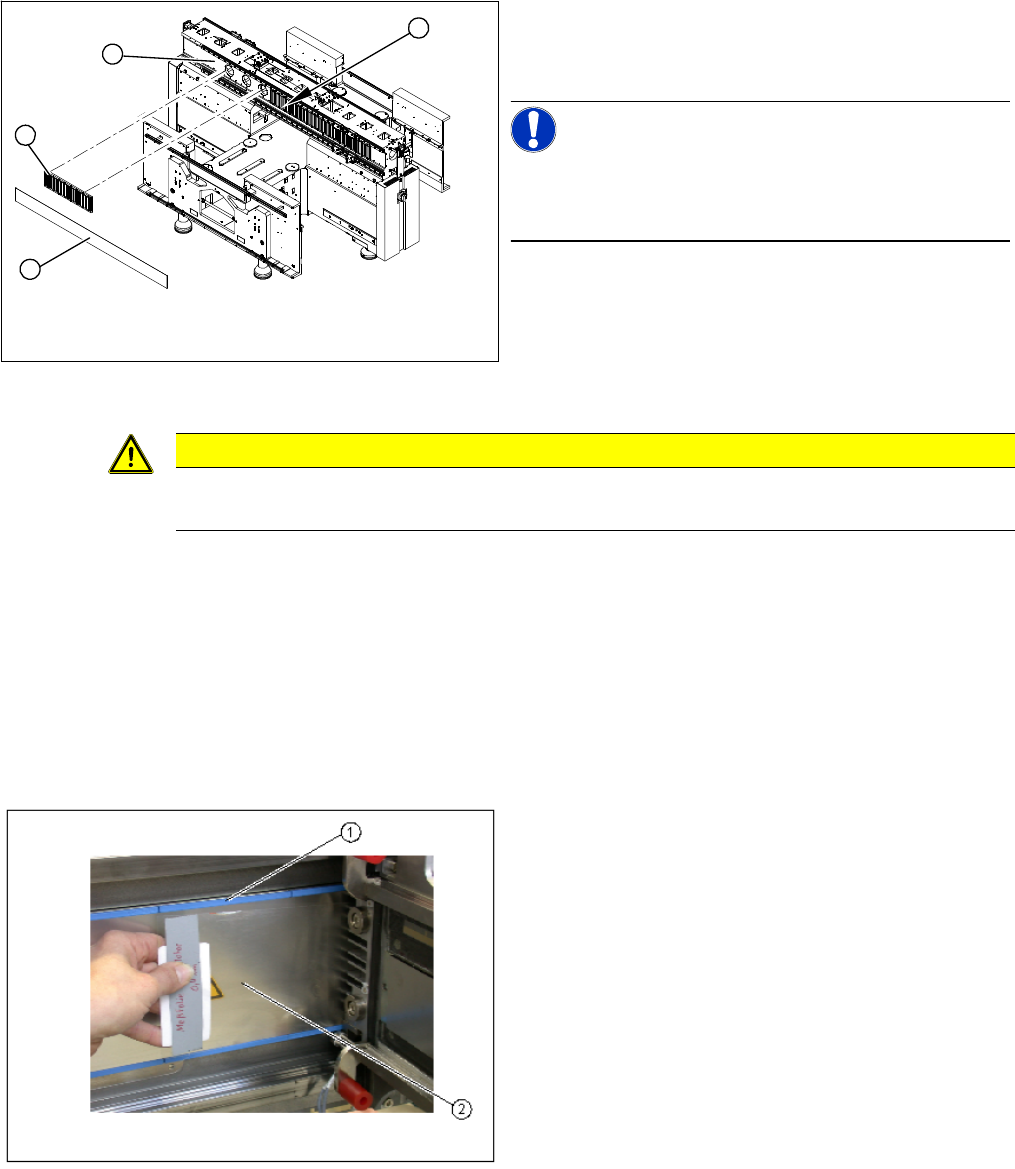
► Carefully rub the contact surfaces (1) of the magnet
with a dressing stone (oil stone) and wipe clean with
a cloth and ethanol.
► Fit the magnetic plate (2).
► Loosely tighten the screws.
► Insert the gauge (2) into the holes provided. This cor
-
rectly sets the distance between the magnetic plates
(1) to 0.8 mm.
► Tighten the screws to a torque of 9.5 N.
4
1
3
2
Service Work
Gantries 3.3.9 Removing the Magnet Cover and Replacing the Magnetic Plates
68 Service Manual (internal version) SIPLACE HF and X Series
► Knock the cover into place with a rubber mallet and block of wood.
► Move the gantry to one side.
► Hook the notch of the magnet cover plate (3) approximately in the center (4).
► Move the gantry over the magnet cover.
► Pull the magnet cover with the aid of a second strong person on both sides and hook in at both ends.
► The magnet cover must lie flat on the magnets. You should not see any unevenness e.g. buckling,
waves.
Installation check
► Check the blue cover for damage and replace if nec
-
essary.
► Attach the blue cover to the fastening screws.
NOTICE!
Production tolerance could mean that the cover will not
lock into place. In this case, sand off a little of the cover
upper edge.
4
1
3
2
CAUTION
Take care that the cover and the magnetic plate are correctly positioned!
The cover must be sit lower than the magnetic plate.
► Move the gantry back and forth. Make sure the gantry
does not rub against the magnet cover or the blue
covers (1).
► Check the 0.4 mm gap between the Y axis drive and
the magnet cover.
► To do this, place the thickness gauge (2) between the
Y axis drive and the magnet cover and then push the
gantry back and forth.
Make sure none of the parts jam or rub.
► Repeat this procedure with a 0.5 mm thickness
gauge. In this case, the gantry may rub against the
warning label.
► Clean the magnet cover with a cloth and ethanol.
► If the gap is not large enough, you will need to remove
the magnet cover and clean everything again.
⇨ Remove the magnetic plate and clean the contact
surface.
⇨ Check the blue cover
Service Work
3.3.10 Replacing the Y Linear Motor - Primary Part Gantries
Service Manual (internal version) SIPLACE HF and X Series 69
3.3.10
3.3.10 Replacing the Y Linear Motor - Primary Part
Replacing the Y Linear Motor - Primary Part
Item number
▪ Linear motor Y drive, complete (D3, X-Series) [03013459-xx]
Removal
Installation
Settings
► Check the axis dynamics of the drives removed.
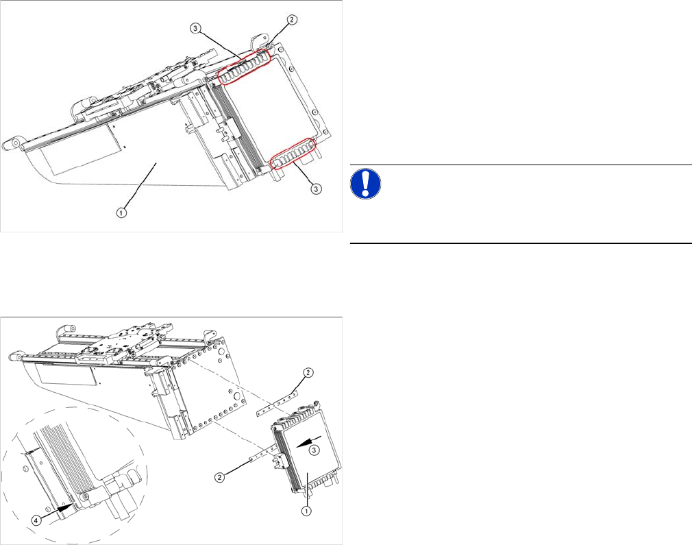
► Dismantle the gantry (see "3.3.3 Replacing Gantries"
[ ➙ 47]) and put it in a suitable place (1).
► Remove the cable ties holding the connection cable.
► Remove the proximity switch mount (2) and proximity
switches.
► Undo the 16 fastening screws (3). Make sure you do
not lose the insulating plates underneath the screws.
These need to be used again later on.
NOTICE!
The fastening screws have been secured with locking
varnish (Loctite 241).
► Loosely fasten the new Y drive (1) with the screws
and insulating plates (2) provided. Use Loctite 241 to
secure them.
► Press the motor upwards, within the tolerance of the
drilling (3). If you do not do this, the motor could lie on
the bottom guides. Now tighten the two center
screws.
► Make sure that the ends of the insulation plates (4)
are not protruding (these plates are not symmetrically
centered). If necessary, press these back in with a
suitable tool (e.g. screwdriver).
► Then tighten all 16 fastening screws with the aid of a
torque wrench (first in the center, then at the top and
lastly at the bottom) (5.5 N).
► Install the proximity switch mount and proximity
switches.
► Fasten the connection cable so that it will not be in the
way when installing the gantry.
► Install the gantry and the trailing cable.