00195655-04_SM_X-Series_FSE_en.pdf - 第78页
Service Work Modular PCB Conveyor System 3.4.3 Replacing the Solenoid Valve f or t he Adjustment Unit [00332940-xx] 78 Ser vice Manual (internal ver sion) SIPLACE HF and X Series 3.4.3 3 . 4 . 3 R e p la c in g t h e S o…
Service Work
3.4.2 Replacing the Stepping Motor of the Width Adjustment System [00367174-xx] Modular PCB Conveyor System
Service Manual (internal version) SIPLACE HF and X Series 77
Removal/Installation
► Unplug the connection cable in the cable duct.
► Fit the new stepping motor and reconnect the system to the electrical system.
► Tension the drive toothed belt.
Position the measuring point of the belt tension device at the strand center (i.e. the longest distance
between two toothed disks) of the conveyor toothed belt.
► Set the tension of the drive toothed belt according to the following values.
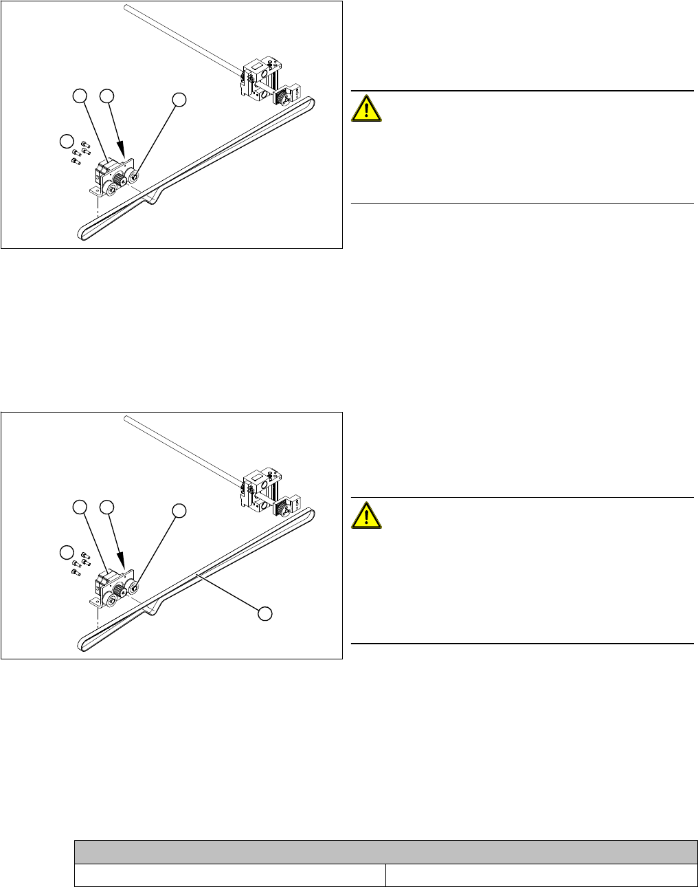
1. Loosening the eccentric axle on the deflection pulley
2. Locknut on the eccentric axle
3. Fastening screws for stepping motor
4. Stepping motor
CAUTION!
Do not damage the toothed belt!
During the following removal and installation of the motor,
the toothed belt for the width adjustment drive must not
be stretched or kinked!
► Move the PCB conveyor to the position which gives
you best access to the stepping motor of the width
adjustment system.
► Move the Y gantries into the area outside the PCB
conveyor.
► Switch off the machine and secure it to prevent unau
-
thorized reactivation.
4
1
3
2
► Loosen the screws fastening the lifting table plate and
remove the lifting table plate from the lifting table unit.
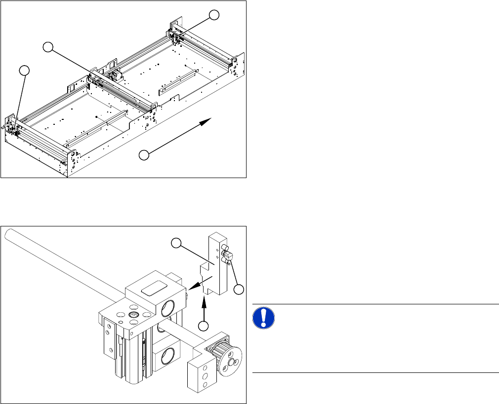
► Loosen the eccentric axle (1) on the deflection pulley
and relieve the tension on the drive toothed belt (5).
CAUTION!
Toothed belt must not come off!
When relaxing the toothed belt, make sure the belt does
not come off (skip) the toothed disks at the 3 adjustment
units. This would cause incorrect alignment of the adjust
-
ment units. Secure these positions with a suitable tool
(screw clamp etc.).
► Remove the 4 fastening screws (3) and then lift out
the stepping motor (4).
4
5
1
3
2
Belt tension- width adjustment
Toothed belt for the drive 24 Hz +/- 2 Hz
Service Work
Modular PCB Conveyor System 3.4.3 Replacing the Solenoid Valve for the Adjustment Unit [00332940-xx]
78 Service Manual (internal version) SIPLACE HF and X Series
3.4.3
3.4.3 Replacing the Solenoid Valve for the Adjustment Unit [00332940-xx]
Replacing the Solenoid Valve for the Adjustment Unit [00332940-xx]
Parts
▪ Solenoid valve with cable, for adjustment unit 1 and 2 [00332940-xx]
Overview
Removal/Installation
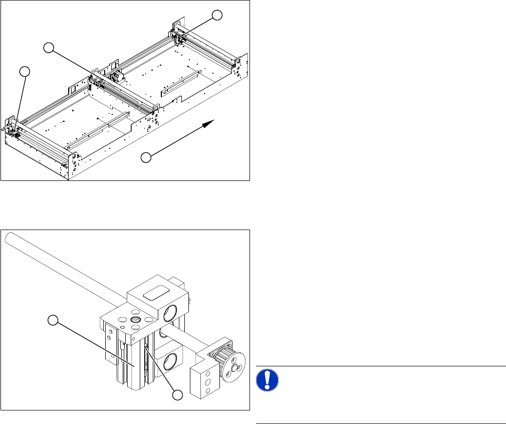
1. Adjustment unit 1
2. Adjustment unit 3
3. Adjustment unit 2
4. Transport direction
► Move the PCB conveyor to the position which gives
you best access to the adjustment system.
► Move the Y gantries into the area outside the PCB
conveyor.
► Switch off the machine and secure it to prevent unau
-
thorized reactivation.
► Switch off the compressed air supply.
3
4
1
2
► Disconnect from the compressed air system (2).
► Loosen the two fastening screws and remove the so
-
lenoid valve (3) from the short-stroke cylinder.
► Unthread the connection cable (1) as far as the rele
-
vant assembly tub conversion board and unplug.
NOTICE!
This might be somewhat complicated depending on the
routing of cables inside the machine base. You may wish
to contact SIPLACE service team regarding this work.
► Fit the new solenoid valve (3) and reconnect the sys
-
tem to the electrical (1) and compressed air (2) sup
-
plies.
1
3
2
Service Work
3.4.4 Replacing the Cylinder Switch for the Adjustment Unit [00369016-xx] Modular PCB Conveyor System
Service Manual (internal version) SIPLACE HF and X Series 79
3.4.4
3.4.4 Replacing the Cylinder Switch for the Adjustment Unit [00369016-xx]
Replacing the Cylinder Switch for the Adjustment Unit [00369016-xx]
Parts
▪ Cylinder switch – adjustment unit 1 [00369016-xx]
▪ Cylinder switch - adjustment unit 2 [00369017-xx]
▪ Cylinder switch - adjustment unit 3 [00365572-xx]
Overview
The cylinder switch on the adjustment unit cylinder should operate when the adjustment unit pin is
pushed out by the pneumatic cylinder and therefore connected to the conveyor side. This signal enables
the width adjustment motor.
Removal/Installation
► Adjust the width until the cylinder switch switches - LED (H36/H37) shines.
Connect the cylinder - i.e. the cylinders are moved upwards, as far as the end stop, using the control
unit.
► Set the cylinder switch so that the LED lights up when it is in engaged mode.
► Fix the position of the cylinder switch (2) with the grub screw.
1. Adjustment unit 1
2. Adjustment unit 3
3. Adjustment unit 2
4. Transport direction
► Move the PCB conveyor to the position which gives
you best access to the adjustment system.
► Move the Y gantries into the area outside the PCB
conveyor.
► Switch off the machine and secure it to prevent unau
-
thorized reactivation.
► Switch off the compressed air supply.
3
4
1
2
► Loosen the grub screw at the cylinder switch (1) and
push the cylinder switch out of the adjustment unit
guide rail (2).
► Unthread the connection cable as far as the conver
-
sion board of the assembly tub.
► Run the connection cable of the new cylinder switch
(2).
► Insert the new cylinder switch into the guide rail.
► Switch the machine on.
NOTICE!
The width adjustment system cylinder switch is set in en
-
gaged mode.
2
1