00195655-04_SM_X-Series_FSE_en.pdf - 第83页
Service Work 3.4.7 Width Adjustment Unit Modular PCB Conveyor System Service Manual (internal ver sion) SIPLACE HF and X Series 83 3.4.7.2 3 . 4 . 7 . 2 S e t t in g t h e P n e u m a t ic C y lin d e r P r o x im it y S…
Service Work
Modular PCB Conveyor System 3.4.7 Width Adjustment Unit
82 Service Manual (internal version) SIPLACE HF and X Series
3.4.7
3.4.7 Width Adjustment Unit
Width Adjustment Unit
3.4.7.1
3.4.7.1 Setting the Proximity Switch on the Adjustment Unit
Setting the Proximity Switch on the Adjustment Unit
Overview
Removal/Installation
► When installing the proximity switch, make sure that this is level with the adjustment unit housing.
► The switching point is set via the actuator on the conveyor side.
► Move the adjustment unit under the conveyor side, then loosen the actuator using the screw.
► Place the distance gauge 0.2 mm on the adjustment unit, press the actuator against the gauge and
fix with the screw.
► Actuators on all conveyor sides have to be checked and adjusted where necessary.
► You then need to calibrate the conveyor sides with the software.
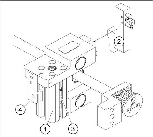
Overview of the proximity switches on the adjustment unit
for width adjustment
1. Short-stroke cylinder
2. Solenoid valve
3. Proximity switch for pneumatic cylinder (for "locking
pin up" recognition)
4. Proximity switch for adjustment unit(for conveyor side
recognition)
▪ The proximity switch (3) serves as a signal for con
-
trolling the pneumatic valve of the adjustment unit.
Once the switching point "conveyor side present" has
been reached, the conveyor side is connected via the
pneumatic valve.
Service Work
3.4.7 Width Adjustment Unit Modular PCB Conveyor System
Service Manual (internal version) SIPLACE HF and X Series 83
3.4.7.2
3.4.7.2 Setting the Pneumatic Cylinder Proximity Switch on the Adjustment Unit
Setting the Pneumatic Cylinder Proximity Switch on the Adjustment Unit
► Start SITEST
► Set any conveyor width. The adjustment units are positioned directly under the conveyor side.
► Start the I/O menu.
► Activate the pneumatic cylinder.
► Set the proximity switch on the pneumatic cylinder so that the LED (H35/H36/H37 for TSP 301) (H64/
65 for TSP 201) shines when connected.
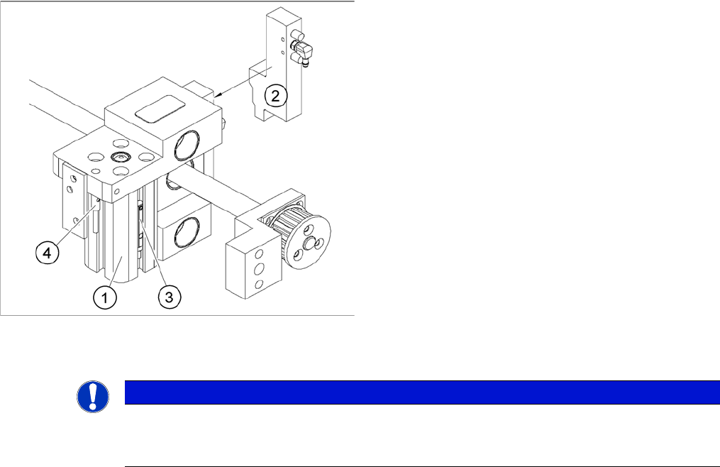
Overview of the proximity switches on the adjustment unit
for width adjustment
1. Short-stroke cylinder
2. Solenoid valve
3. Proximity switch for pneumatic cylinder (for "locking
pin up" recognition)
4. Proximity switch for adjustment unit(for conveyor side
recognition)
The proximity switch (3) on the adjustment unit cylinder
should operate when the adjustment unit pin is pushed
out by the pneumatic cylinder and therefore connected to
the conveyor rail. This signal enables the width adjust
-
ment motor.
NOTICE
Setting
The proximity switch on the pneumatic cylinder is set in its engaged state.
The proximity switch is off when the cylinder is extended into free space.
Service Work
C&P20 Placement Head 3.5.1 Replacing the E/D Transformer (Collector Ring) - FSE
84 Service Manual (internal version) SIPLACE HF and X Series
3.5
3.5 C&P20 Placement Head
C&P20 Placement Head
3.5.1
3.5.1 Replacing the E/D Transformer (Collector Ring) - FSE
Replacing the E/D Transformer (Collector Ring) - FSE
Preparation
NOTICE
The star is not a spare part!
The star is not a spare part and is only removed if the E/D transformer needs to be replaced.
CAUTION
Different E/D transformer used for CP20 / CP20A!
The E/D transformer is used for the C&P20 [03007711-xx].
Only the E/D transformer may be used on the C&P20A of the X4I [03058629-xx]!
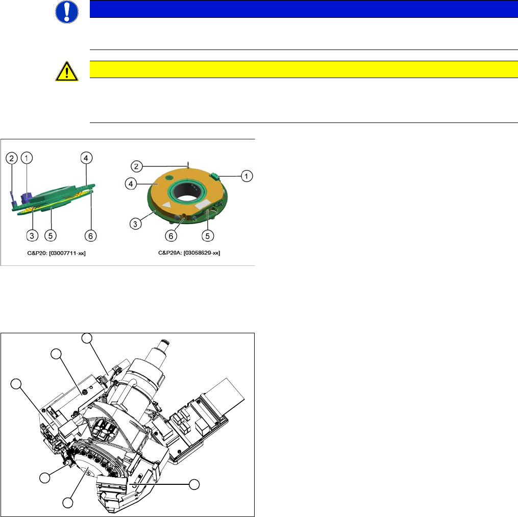
Old and new ED transformers
▪ The new E/D transformer [03058629-xx] consists of a
stationary and a rotating part.
Three sliding contacts (5) transmit the direct current
voltage (24V/4A).
▪ The CAN bus signals are transmitted contactless.
▪ Connector (1) to intermediate distributor
▪ A centering pin (2) fixes the stationary part (4) in
place.
▪ The rotating part (3) is fixed to the star carrier with five
screws, which can be loosened via the service open
-
ing (6).
1. Component camera
2. Silencer
3. BE-sensor
4. Z axis
5. Pressure control valve
6. Return unit
► Remove the component camera (1).
► Remove the silencer (2).
► Remove the pressure control valve (5).
► Remove the Z axis (4) with return unit (6).
► Remove the component sensor (3).
6
1
5
4
3
2