00195655-04_SM_X-Series_FSE_en.pdf - 第92页
Service Work C&P20 Placement Head 3.5.2 Settings the C&P20 (FSE) Jaws 92 Ser vice Manual (internal ver sion) SIPLACE HF and X Series Setting the jaws ► Make s ure that th e Z axis is lo cated betwe en the two seg…
Service Work
3.5.2 Settings the C&P20 (FSE) Jaws C&P20 Placement Head
Service Manual (internal version) SIPLACE HF and X Series 91
Fitting the setting gauge
Moving the Z axis arms out
► Rotate the star so that the jaws/arms of the Z axis are
centered between the two segments, without dead in
-
dexing plates.
► Move the Z axis out without the segment.
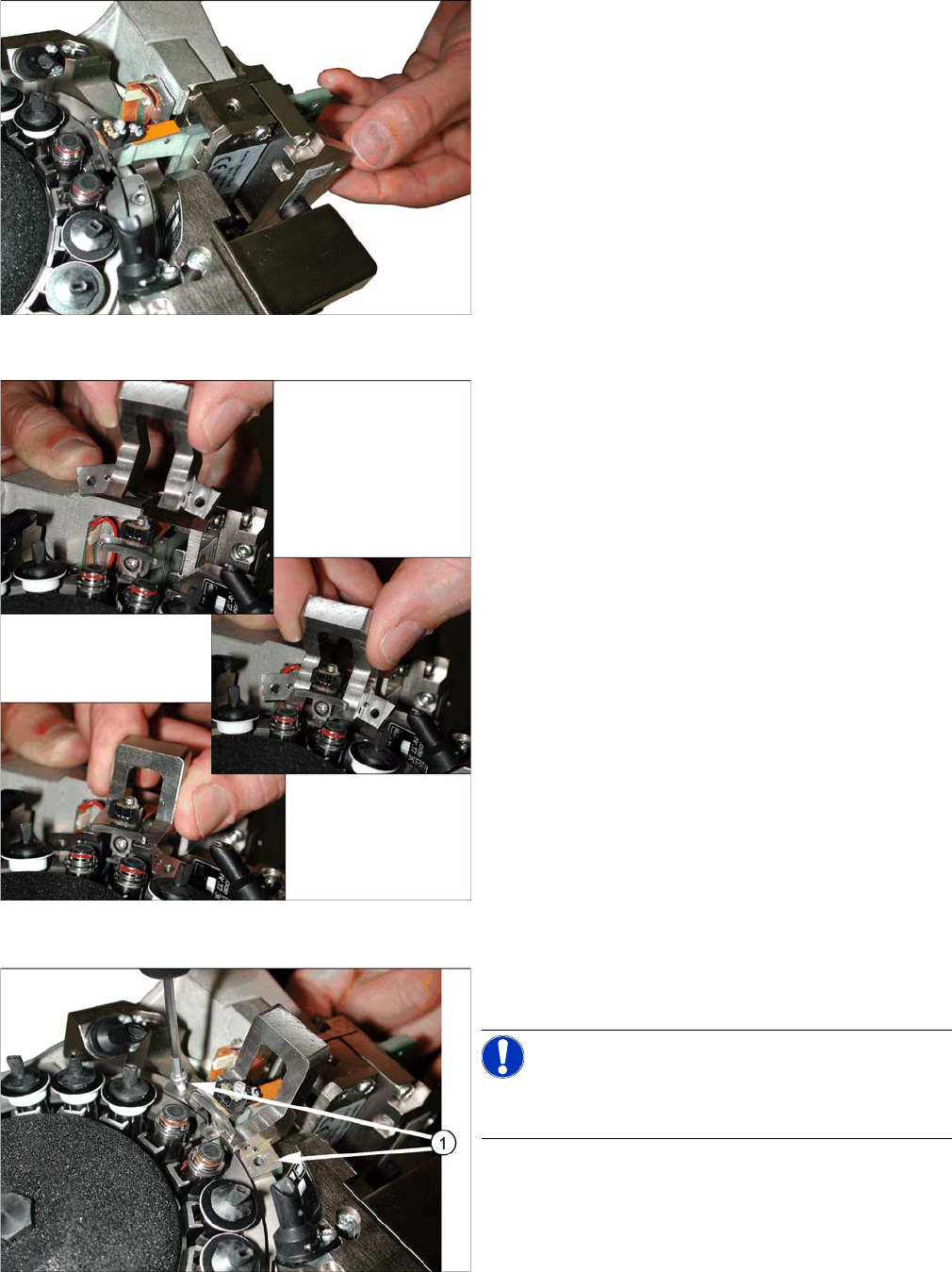
Fitting the setting gauge
► Place the jaw gauge on the raceway, ensuring that
the jaws lie flat on the contact surfaces.
Press the jaw gauge against the holes drilled in the
raceway, so that the centering pins engage with the
relevant holes.
Fixing the setting gauge with the M2.5x12 mm screws
► Fasten the gauge with the screws (1) from the service
kit (M2.5x12 mm).
NOTICE!
Do not use the original raceway screws to fix the setting
gauge! These are too short and could damage the thread!
Service Work
C&P20 Placement Head 3.5.2 Settings the C&P20 (FSE) Jaws
92 Service Manual (internal version) SIPLACE HF and X Series
Setting the jaws
► Make sure that the Z axis is located between the two segments without dead indexing plates and
that you can see the Phillips screw.
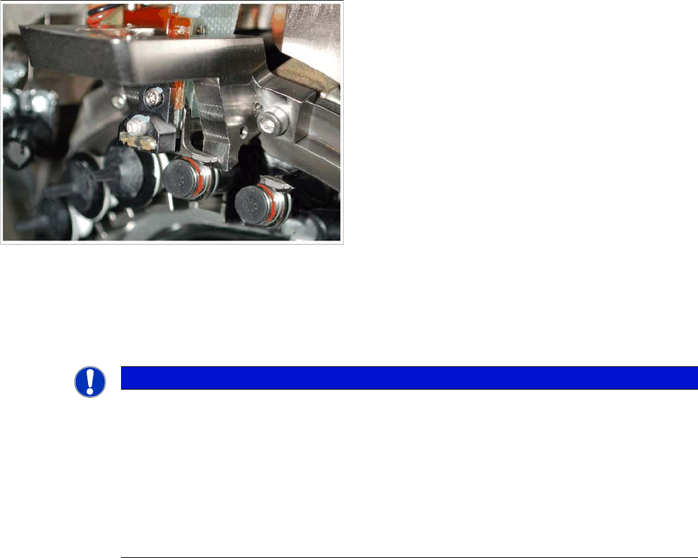
Fitting the setting gauge onto the C&P20 head
NOTICE
If
► The side stopper (stop pin) of the gauge presses against the jaws so that these can not be
moved.
Procedure: if it is not possible to push the 0.04 feeler gauge between the jaws and the stop
pin of the gauge, make sure that the jaws lie flat against contact surfaces 2a and 2b of the
gauge.
► The jaws can not be pressed against the side stop (stop pin) of the gauge.
Procedure: In this case, push the jaws as far as possible towards the stop pin. Do not push
the jaws with force against the stop pin of the gauge.
Service Work
3.5.2 Settings the C&P20 (FSE) Jaws C&P20 Placement Head
Service Manual (internal version) SIPLACE HF and X Series 93
Final work
► Attach the two new dead indexing plates (not the ones you removed, these could be damaged). At
-
tach nozzles, if required.
► Remove the hose piece from the return unit.
► Fit the remaining parts and install the head in the machine.
► Connect all cables and hoses.
► Switch the placement machine on.
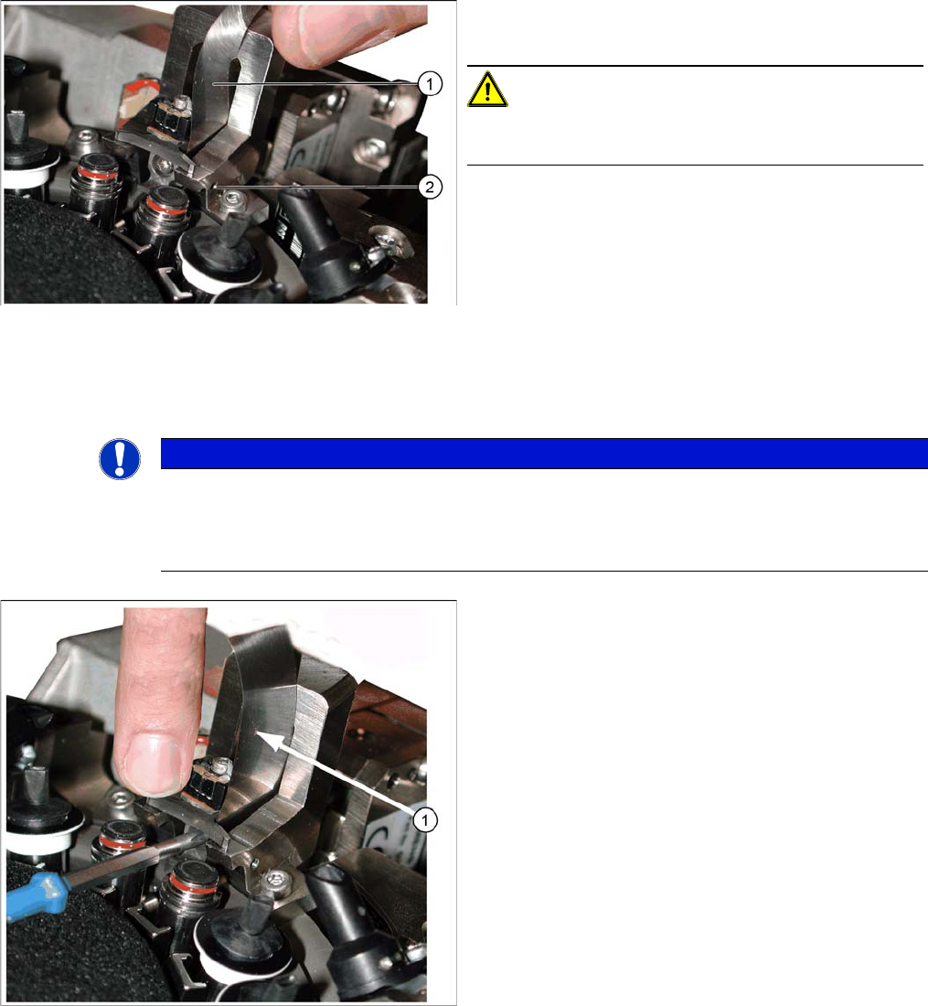
Correct setting with feeler gauge
1. Feeler gauge 0.04 mm
2. Stop pin (drilling for pin, view from outside)
CAUTION!
The stop pin is fixed with adhesive. Do not adjust the stop
pin.
► Place a 0.04 mm feeler gauge between the jaws and
the side stop in the setting gauge.
► Move the jaws so that they are against the two con
-
tact surfaces and the side stop (stop pin) + feeler
gauge.
► Hold the jaws in this position and tighten the Phillips
screw with the torque wrench (torque 35 Ncm) (see
next diagram).
NOTICE
Snap jaws
Make sure that the jaws lie flat against the contact surfaces and the side stop and do not turn.
Use the 0.01 feeler gauge to check that the jaws are really against the contact surfaces of the
gauge (through own weight).
Tightening the screws fastening the jaws
► Pull out the feeler gauge (1) and test with the 0.01
feeler gauge. This should fit easily between the stop
pin and the jaws.
► Carefully tip the setting gauge to remove it, without
hitting the jaws.
► Feed the segment ball bearing back into the Z axis
jaws.