00195655-04_SM_X-Series_FSE_en.pdf - 第96页
Service Work C&P20 Placement Head 3.5.3 Replacing the Component Sensor (FSE) [03006742-xx] 96 Ser vice Manual (internal ver sion) SIPLACE HF and X Series 3.5.3 3 . 5 . 3 R e p la c in g t h e C o m p o n e n t S e n …

Service Work
3.5.2 Settings the C&P20 (FSE) Jaws C&P20 Placement Head
Service Manual (internal version) SIPLACE HF and X Series 95
Troubleshooting - calibration of zero point correction
If calibration was not successful:
1. Check the Z axis path.
The max. and min. travel of the Z axis (C&P20) is 34000 digits and -200 digits.
2. Error message: FM 19127 – Values calculated for the zero point correction exceed the tolerance lim
-
its.
This means that the angle of the Z axis is outside the threshold values.
Solution: Use the setting gauge to set the jaws on the C&P20 head.
NOTICE
Procedure
If the jaws have already been set, proceed as follows:
► Dismantle the placement head as described above and fit the setting gauge, without loos
-
ening the screw fastening the jaws beforehand.
► Use the 0.01 mm feeler gauge to check whether the jaws are really placed against the con
-
tact surfaces 2a and 2b. If this is the case, loosen the screw fastening the jaws and place
two 0.01 mm feeler gauges between the jaws and contact surface 2a, so that they are just
clamped in between the jaws and the setting gauge.
Service Work
C&P20 Placement Head 3.5.3 Replacing the Component Sensor (FSE) [03006742-xx]
96 Service Manual (internal version) SIPLACE HF and X Series
3.5.3
3.5.3 Replacing the Component Sensor (FSE) [03006742-xx]
Replacing the Component Sensor (FSE) [03006742-xx]
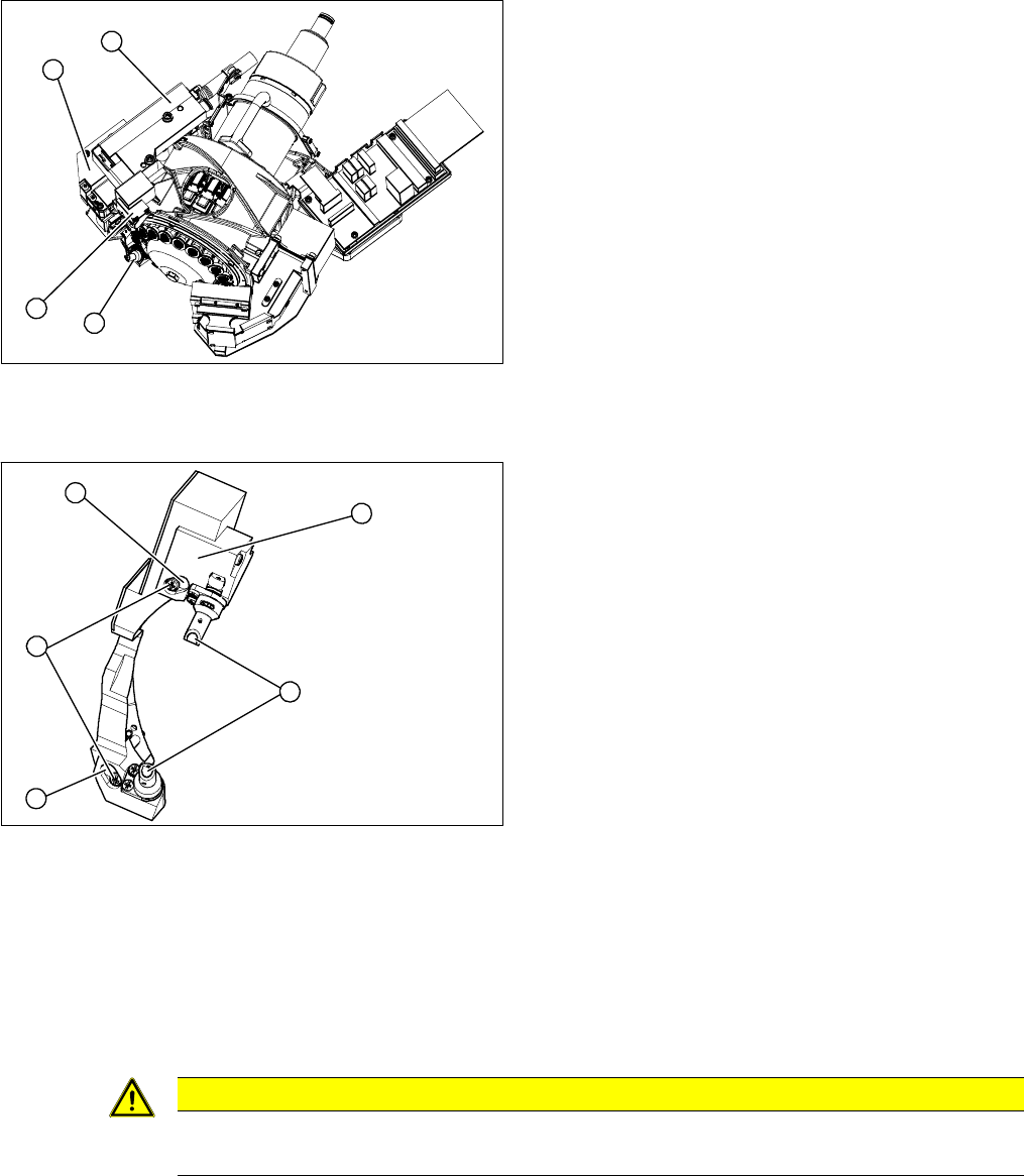
Overview
Removal/Installation
► Unplug the electrical connection to the intermediate distributor. Remove any cable ties.
► Loosen the two fastening screws (4) and remove the complete component sensor (3).
⇨ The components of the transmitter/receiver unit are coordinated with one another. Only loosen
the two fastening screws, otherwise the component sensor will no longer function properly.
► Make sure that you do not damage or contaminate the lens system of the transmitter/receiver unit
(2).
► Install the new component sensor (3).
► Reconnect to the electricity system. Fasten the cable with cable ties.
► Fit the Z axis with return unit and the pressure control valve.
► Perform a reference run. Please refer to the adjustment instructions.
1. Component sensor
2. Z axis cover
3. Z axis with return unit
4. Pressure control valve
► Remove the pressure control valve (4). This gives
you access to the Z drive
► Remove the Z axis cover (2).
► Remove the Z axis (3) and return unit.
► You can now access the component sensor (1).
1
4
3
2
1. 2 x locking screws, behind: fastening screws
2. Lens system of transmitter/receiver unit
3. Complete component sensor
4. 2 x fastening screws
4
4
1
3
2
CAUTION
Torque
Tighten the screws to a torque of 130 Ncm.
Service Work
3.5.4 Replacing the Z Axis (FSE) [03005155-xx] C&P20 Placement Head
Service Manual (internal version) SIPLACE HF and X Series 97
3.5.4
3.5.4 Replacing the Z Axis (FSE) [03005155-xx]
Replacing the Z Axis (FSE) [03005155-xx]
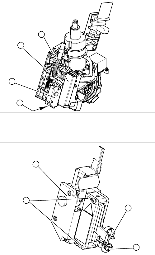
Overview
Overview of Z axis
1. Pressure control valve
2. Return unit
3. Z axis
4. Z axis cover
► Remove the pressure control valve (1). This gives
you access to the Z axis.
► Loosen the two screws fastening the return unit (2)
and unplug the electrical supply at the solenoid valve
and the hose at the compressed air connection.
► Remove the complete return unit (2).
1
3
2
4
1. Complete Z axis
2. 2 x fastening screws
3. Light barrier Z axis down
4. Snap jaws
1
4
3
2