00195655-04_SM_X-Series_FSE_en.pdf - 第97页
Service Work 3.5.4 Replacing the Z Axis (FSE) [03005155-xx] C&P20 Placement H ead Service Manual (internal ver sion) SIPLACE HF and X Series 97 3.5.4 3 . 5 . 4 R e p la c in g t h e Z A x is ( F S E ) [ 0 3 0 0 5 1 5…
Service Work
C&P20 Placement Head 3.5.3 Replacing the Component Sensor (FSE) [03006742-xx]
96 Service Manual (internal version) SIPLACE HF and X Series
3.5.3
3.5.3 Replacing the Component Sensor (FSE) [03006742-xx]
Replacing the Component Sensor (FSE) [03006742-xx]
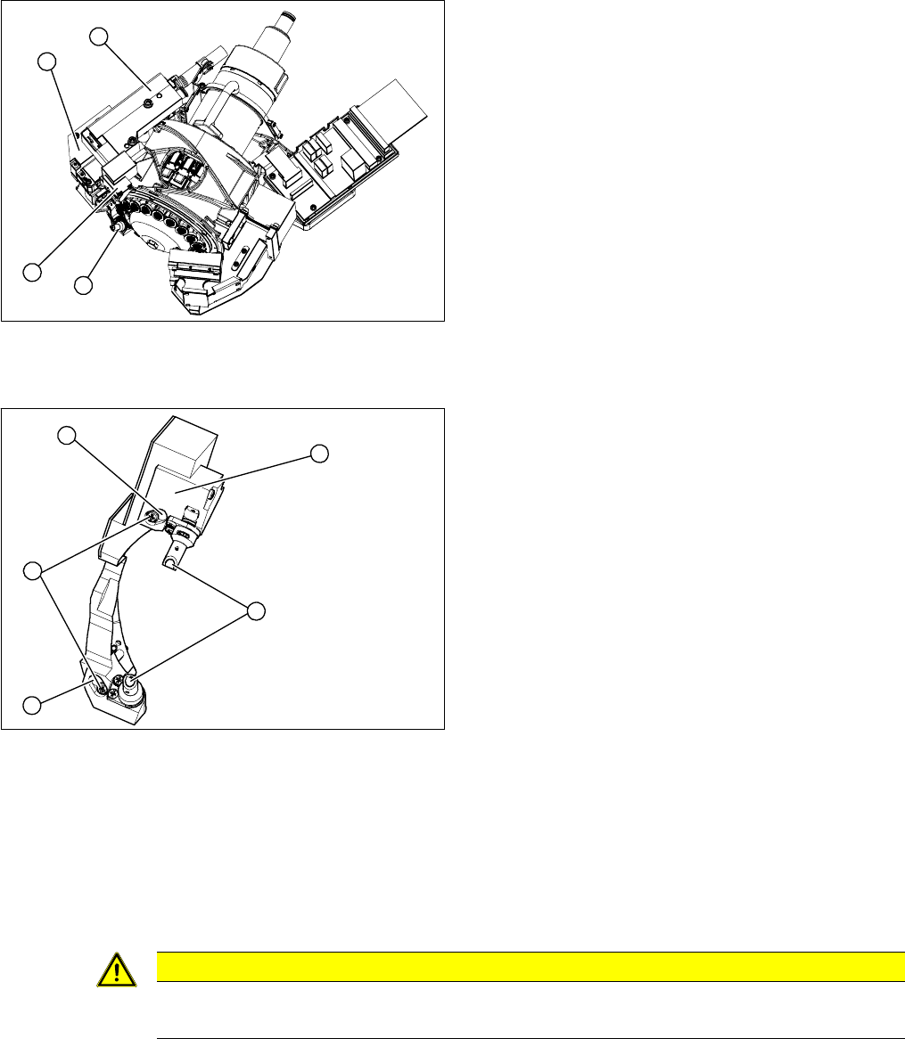
Overview
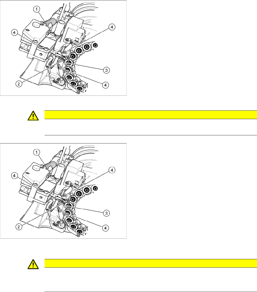
Removal/Installation
► Unplug the electrical connection to the intermediate distributor. Remove any cable ties.
► Loosen the two fastening screws (4) and remove the complete component sensor (3).
⇨ The components of the transmitter/receiver unit are coordinated with one another. Only loosen
the two fastening screws, otherwise the component sensor will no longer function properly.
► Make sure that you do not damage or contaminate the lens system of the transmitter/receiver unit
(2).
► Install the new component sensor (3).
► Reconnect to the electricity system. Fasten the cable with cable ties.
► Fit the Z axis with return unit and the pressure control valve.
► Perform a reference run. Please refer to the adjustment instructions.
1. Component sensor
2. Z axis cover
3. Z axis with return unit
4. Pressure control valve
► Remove the pressure control valve (4). This gives
you access to the Z drive
► Remove the Z axis cover (2).
► Remove the Z axis (3) and return unit.
► You can now access the component sensor (1).
1
4
3
2
1. 2 x locking screws, behind: fastening screws
2. Lens system of transmitter/receiver unit
3. Complete component sensor
4. 2 x fastening screws
4
4
1
3
2
CAUTION
Torque
Tighten the screws to a torque of 130 Ncm.
Service Work
3.5.4 Replacing the Z Axis (FSE) [03005155-xx] C&P20 Placement Head
Service Manual (internal version) SIPLACE HF and X Series 97
3.5.4
3.5.4 Replacing the Z Axis (FSE) [03005155-xx]
Replacing the Z Axis (FSE) [03005155-xx]
Overview
Overview of Z axis
1. Pressure control valve
2. Return unit
3. Z axis
4. Z axis cover
► Remove the pressure control valve (1). This gives
you access to the Z axis.
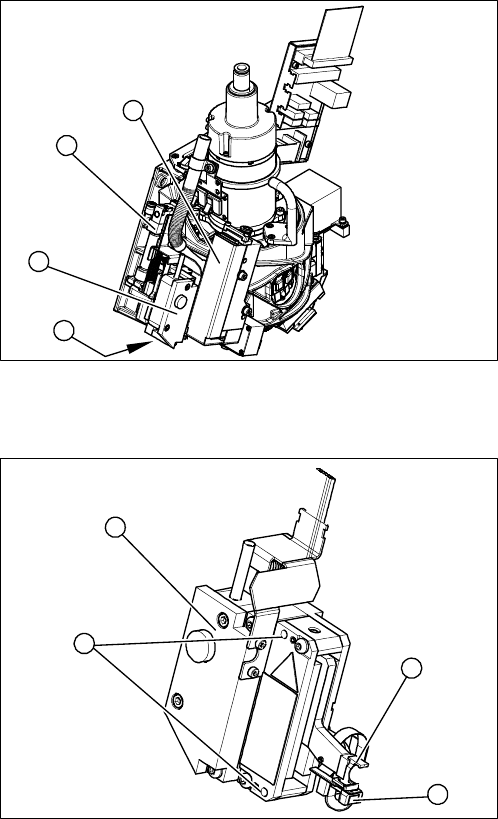
► Loosen the two screws fastening the return unit (2)
and unplug the electrical supply at the solenoid valve
and the hose at the compressed air connection.
► Remove the complete return unit (2).
1
3
2
4
1. Complete Z axis
2. 2 x fastening screws
3. Light barrier Z axis down
4. Snap jaws
1
4
3
2
Service Work
C&P20 Placement Head 3.5.4 Replacing the Z Axis (FSE) [03005155-xx]
98 Service Manual (internal version) SIPLACE HF and X Series
Removal/installation
1. Fastening screw for Z axis
2. Snap jaws
3. Ball bearings for DP drive
4. 3 x fastening screws for Z axis cover
► Remove the 3 screws fastening the Z axis cover (4).
You can now access the Z axis from below.
► Remove the nozzles and dead indexing plates from
two neighboring segments. so that the Z axis can be
unthreaded more easily.
► Loosen the screw (1) fastening the Z axis.
► Rotate the star into its central position.
► Move the Z axis downwards and unthread the snap
jaws (2) from the ball bearings (3) of the DP drive.
CAUTION
Check how the cables are run!
Make sure that you do not touch or damage the flex cable.
► Remove the cable ties and unplug the cable from the
intermediate distributor.
⇨ Track signals incremental encoder
⇨ Light barrier down
⇨ Linear motor
► Thread in the snap jaws (2) of the new Z axis, at the
DP drive ball bearing (3). The snap jaws must en
-
gage.
► Reconnect to the electricity system. Fasten the cable
with cable ties.
► While fastening the screws, push the Z axis unit
against the stopper.
► Fit the return unit and the pressure control valve.
► Start SITEST and perform zero point correction by
means of a reference run.
CAUTION
Checking the snap jaws
After replacing the Z axis, you need to check the snap jaws.
► For details, see the setting instructions for the snap jaw gauge.