00192211-02_RI_ObliqueLighting - 第28页
Retrofit Instructions Oblique Lighting for SIPLACE 80 S-20 /F4/S-23/ F5 /HS-50/HF 8.4 Moving In the Movable Component Changeover Table 05/15 Issue 30 8.4 Moving In the Movable Component Changeover Ta b l e (Note: Y o u w…
Oblique Lighting for SIPLACE 80 S-20 /F4/S-23/ F5 /HS-50/HF Retrofit Instructions
05/15 Issue 8.3 Installing the Oblique Lighting
29
► S23/HS50: Fasten the 2 cables to the cable harness with additional cable ties (see Fig. 8.3.9).
► S23/HS50: Screw the cover back on the placement head.
Note: You will find additional information regarding HS-50 in Section 5. 8
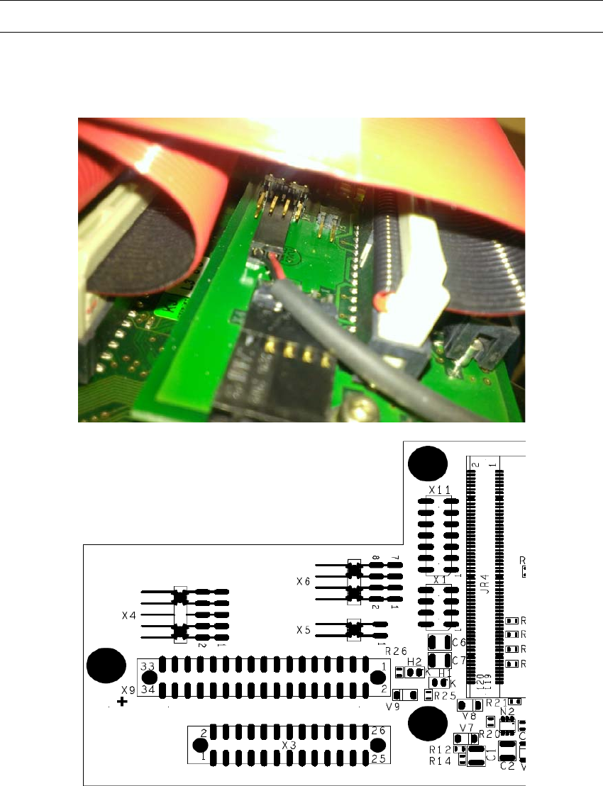
► HF: Plug the 2-pin connector onto the X6 plug of the vision board (see Fig. 8.3.10).
8
Fig. 8.3.10 Vision board X6 plug
Retrofit Instructions Oblique Lighting for SIPLACE 80 S-20 /F4/S-23/ F5 /HS-50/HF
8.4 Moving In the Movable Component Changeover Table 05/15 Issue
30
8.4 Moving In the Movable Component Changeover
Table
(Note: You will find detailed instructions in the User Manual for the placement machine.) 8
► Push the movable component changeover table back into the placement machine somewhat
and connect the 2 cables and the compressed air hose.
► Turn the placement machine ON at the main switch.
► Lift the movable component changeover table and push it all the way in.
► Lift it completely one more time and then let it sink onto the centering pin (and fasten it in
place).
► Close the safety hood.
8.5 Moving In the Component Changeover Table
► Make certain that the contact surfaces of the component changeover table and the machine
are clean.
► Use the pallet jack to pick up a component changeover table and then lift the table until it will
not hang up anywhere when it is pushed into the machine.
► Carefully push the component changeover table into the machine until the component change-
over table centering pin location holes are over the centering pins.
► Carefully lower the component changeover table until the it is resting on the receiver of the ma-
chine frame.
► Close the tension lever.
► Next, plug in the flat connector for the communication signals.
► Insert the 2 socket hex head cap screws and tighten them.
► Plug in the round connector for the power. Close the safety hoods.
Oblique Lighting for SIPLACE 80 S-20 /F4/S-23/ F5 /HS-50/HF Retrofit Instructions
05/15 Issue 8.5 Moving In the Component Changeover Table
31
9Software
9
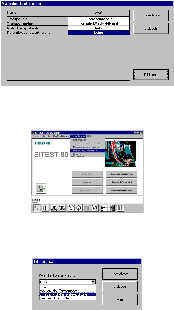
Fig. 9.0.1 Menu: "Configure the Machine"
► At the station computer, select "Settings" in the SITEST program and then "Machine configu-
ration".
9
Fig. 9.0.2 SITEST Program Menu: "Basic View of Machine"
► Mark "Ceramic substrate centering" with a double click and then mark the option "Additional
PCB camera lighting" in the editing box.
9
Fig. 9.0.3 Menu: "Ceramic Substrate Centering"