00194474-0702_AI_HeadReconfig_X_605_DE+EN.pdf - 第180页
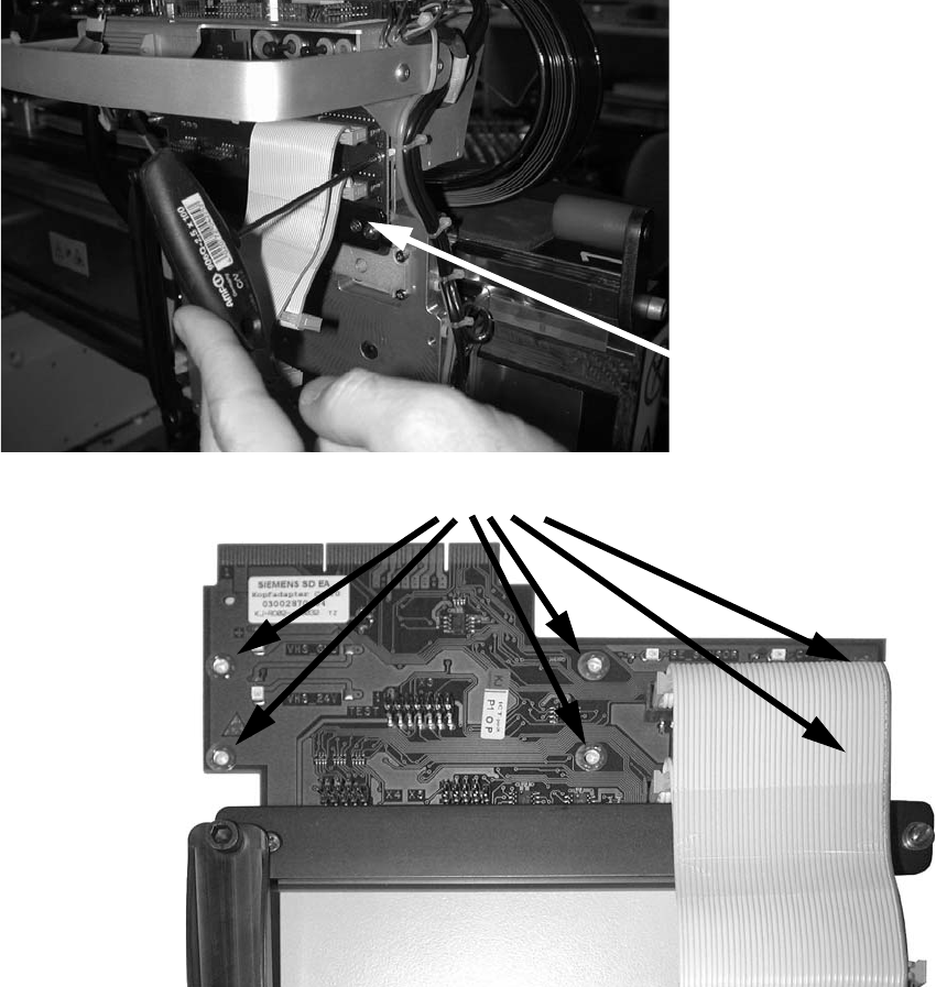
2 Assembly Instructions - SIPLACE X-Series Head Reconfiguration Kits Head Reconfiguration Kits 07/2010 Edition 180 : Remove the head adapter bo ard (6 screws). 2 2 2 2 2 2 2 Head adapter board 6 screws
Head Reconfiguration Kits 2 Assembly Instructions - SIPLACE X-Series Head Reconfiguration Kits
07/2010 Edition
179
2
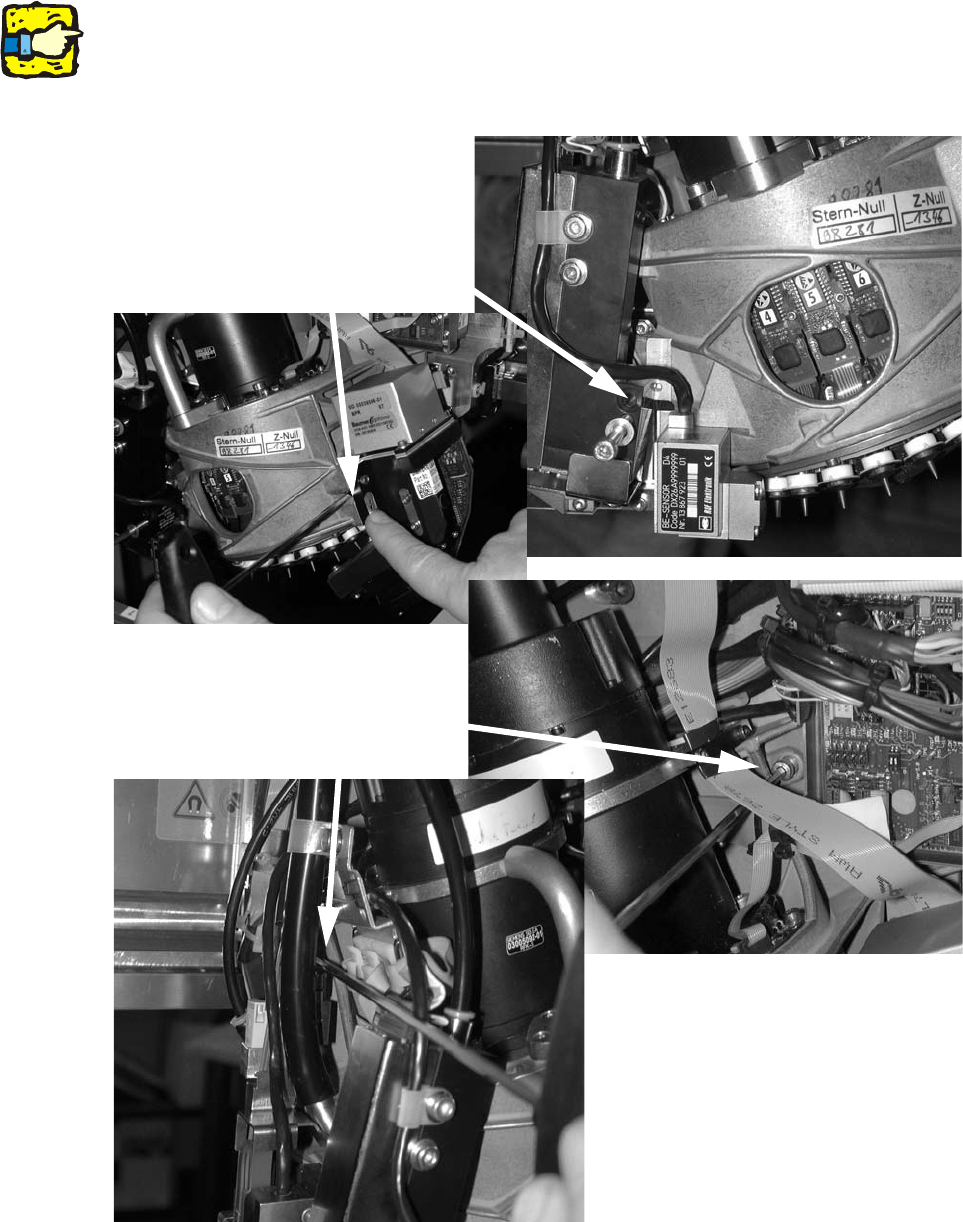
As you remove the fixing screws, hold the placement head firmly to prevent it falling and thus avoid
possible damage. 2
: Loosen the four fixing screws on the placement head and remove the placement head.
2
2
Loosen the cap screws
Loosen the cap screws
2 Assembly Instructions - SIPLACE X-Series Head Reconfiguration Kits Head Reconfiguration Kits
07/2010 Edition
180
: Remove the head adapter board (6 screws).
2
2
2
2
2
2
2
Head adapter board
6 screws

Head Reconfiguration Kits 2 Assembly Instructions - SIPLACE X-Series Head Reconfiguration Kits
07/2010 Edition
181
2.11 Installing the C&P 6/12 placement head
2
Crash DANGER: If the C&P 6/12 is combined with a TwinHead in a 2 gantries placement area the
stationary camera for the TwinHead must be installed offset downwards. See also Chapter
2.12.1. 2
2
Risk of crash: fit the upper light barrier on tray supply 1 of the MTC2 when the C&P6/12 head
should pick-up components from an MTC2. Read the "Assembly instructions: MTC2 - component
trolley" (00193897-) also. 2
2.11.1 Installing the nozzle changer
: To install the nozzle changer, please read the assembly instructions for the X series nozzle
changer (item no.:00194482-).
2
Risk of a head crash: always run the placement heads with the appropriate nozzle changer. The
wrong nozzle changer causes a risk of a head crash.
2
2
On the subject of the reject bin sensor, also read the
assembly instructions for the reject bin sensor, SIPLACE HF series / X series (item no.:00194550-
).
2