00194474-0702_AI_HeadReconfig_X_605_DE+EN.pdf - 第187页
Head Reconfiguration Kits 2 Assemb ly Instructions - SIPLACE X-Series Head Reconfiguration Kits 07/2010 Edition 187 : If problems occur with the CAN bus, measu re the resist ance between pin 7 (CAN High) and pin 2 (CAN L…
2 Assembly Instructions - SIPLACE X-Series Head Reconfiguration Kits Head Reconfiguration Kits
07/2010 Edition
186
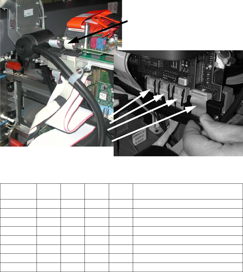
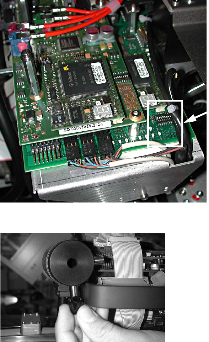
: Plug the camera cable into the head interface board (see photograph).
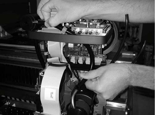
: Plug the four ribbon cables into the step motor board. Make sure that the polarization is correct.
2
: Check the jumper settings on the C500 head interface board.
Jumper
Gantry
1
Gantry
2
Gantry
3
Gantry
4
1
0 1 0 1 Gantry ID0
2
0 0 1 1 Gantry ID1
3
1 1 1 1 120 Ohm CAN terminating resistor
4
0 0 0 0 Boot
5
0 0 0 0 Reset
6
0 0 0 0 CAN ID0
7
0 0 0 0 CAN ID1
8
0 0 0 0 Write protect deactivated
Component camera cable
Head Reconfiguration Kits 2 Assembly Instructions - SIPLACE X-Series Head Reconfiguration Kits
07/2010 Edition
187
: If problems occur with the CAN bus, measure the resistance between pin 7 (CAN High) and
pin 2 (CAN Low). It should be 60 Ohm.
2
: Fit the cap (type D Di8.0 H15 flexible PVC, item no. 03006728-) on the exhaust air damper.
Jumper
position
2 Assembly Instructions - SIPLACE X-Series Head Reconfiguration Kits Head Reconfiguration Kits
07/2010 Edition
188
: Connect the top and bottom hoses.
2.11.3 Connections on the compressed air distributor
There are currently two different pneumatic distributors available depending on the cable and
hose carrier installed:
– Use the old cable and hose carrier on CFK gantries 02 and 04 for the old pneumatic distributor
and
– the new pneumatic distributor for the "CFK 06 gantry, new cable and hose carrier". These new
distributors are prepared for the vacuum pump on the C&P 20 head option.