00194474-0702_AI_HeadReconfig_X_605_DE+EN.pdf - 第188页
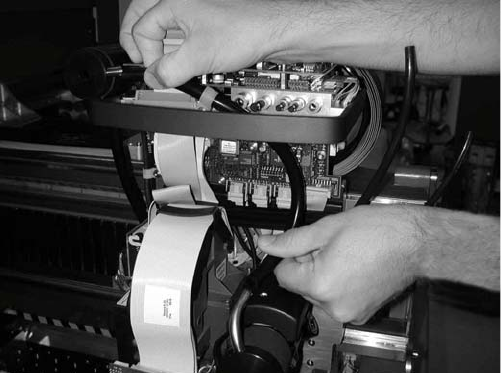
2 Assembly Instructions - SIPLACE X-Series Head Reconfiguration Kits Head Reconfiguration Kits 07/2010 Edition 188 : Connect the top and bottom hoses. 2.1 1.3 Connections on the co mpressed air distributor There are curr…
Head Reconfiguration Kits 2 Assembly Instructions - SIPLACE X-Series Head Reconfiguration Kits
07/2010 Edition
187
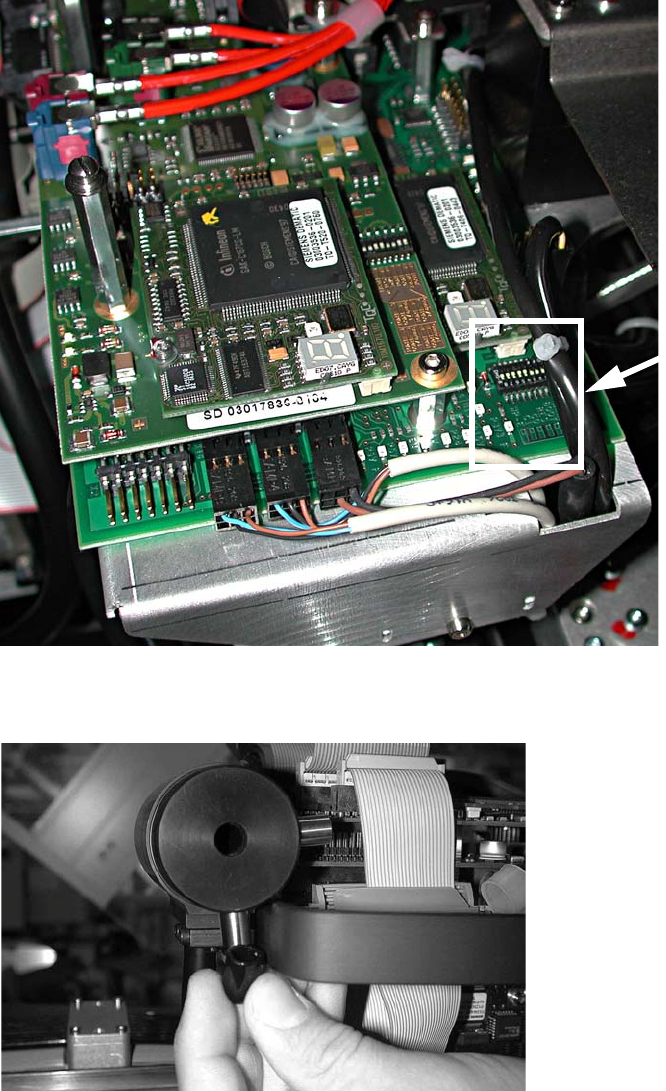
: If problems occur with the CAN bus, measure the resistance between pin 7 (CAN High) and
pin 2 (CAN Low). It should be 60 Ohm.
2
: Fit the cap (type D Di8.0 H15 flexible PVC, item no. 03006728-) on the exhaust air damper.
Jumper
position
2 Assembly Instructions - SIPLACE X-Series Head Reconfiguration Kits Head Reconfiguration Kits
07/2010 Edition
188
: Connect the top and bottom hoses.
2.11.3 Connections on the compressed air distributor
There are currently two different pneumatic distributors available depending on the cable and
hose carrier installed:
– Use the old cable and hose carrier on CFK gantries 02 and 04 for the old pneumatic distributor
and
– the new pneumatic distributor for the "CFK 06 gantry, new cable and hose carrier". These new
distributors are prepared for the vacuum pump on the C&P 20 head option.
Head Reconfiguration Kits 2 Assembly Instructions - SIPLACE X-Series Head Reconfiguration Kits
07/2010 Edition
189
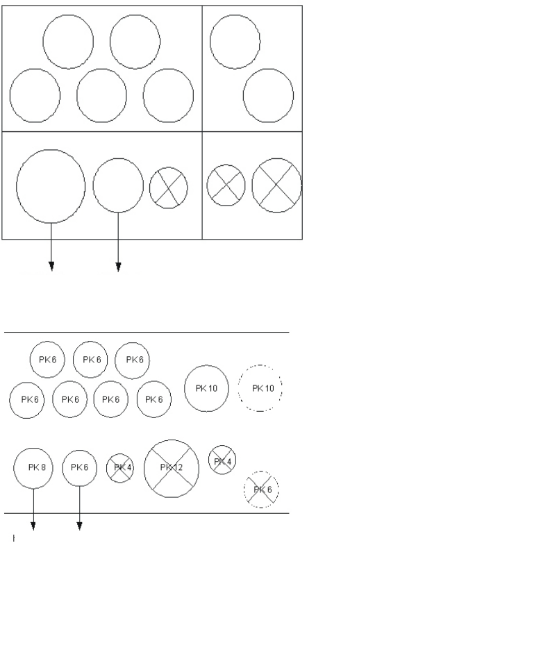
Gantries CFK 02 and CFK 04
Gantry CFK 06
Plug QSC-6H Item no. 00337891-
Plug QSC-4H Item no. 00330249-
Plug QSC-8H Item no. 03010908-
Plug QSC-10H Item no. 00324874-
Plug QSC-12H Item no. 03015210-
Up to machine serial
no. B-078
Holding circuit Pickup circuit
Pneumatic distributor back
Input:
7x pneumatic hose
Pneumatic distributor front
Output:
DLM head 6/12
Holding circuit Pickup circuit
Pneumatic distributor back
Input:
7x pneumatic hose (PK6)
2x pneumatic hose
vacuum pump option (PK10)
Pneumatic distributor front
Output:
DLM head 6/12
From machine serial
no. B-079