00194474-0702_AI_HeadReconfig_X_605_DE+EN.pdf - 第200页
2 Assembly Instructions - SIPLACE X-Series Head Reconfiguration Kits Head Reconfiguration Kits 07/2010 Edition 200 2.12.2 Connecting the cameras 2.12.2.1 Up to machine serial number B325 and "CO camera, stat. P&…
Head Reconfiguration Kits 2 Assembly Instructions - SIPLACE X-Series Head Reconfiguration Kits
07/2010 Edition
199
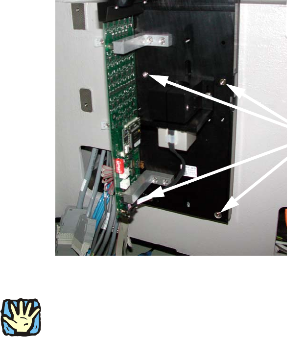
: Place the base plate of the camera on the "Partition plate for the fiducial" so that both set
screws are accessible and screw down tight using two screws DIN912 M6x35 - 8.8 (item no.
00845062-).
2
: Now replace both set screws with bolts.
2
If this is not possible, the camera must be removed again and the set screws replaced with suit-
able items. There must be no setscrew hidden behind the camera since the latter can possibly be
mounted askew because of this. 2
2
2
2
2
2
2
2
2
2
2
2
4 screws
2 Assembly Instructions - SIPLACE X-Series Head Reconfiguration Kits Head Reconfiguration Kits
07/2010 Edition
200
2.12.2 Connecting the cameras
2.12.2.1 Up to machine serial number B325 and "CO camera, stat. P&P (TYPE33) 55x45
digit." (item no.: 03016339-) < 04
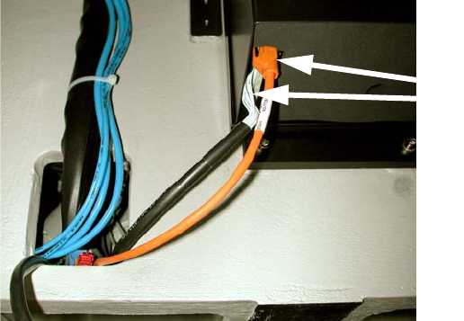
: Pull the two connecting cables (vision control and hot link cable) for the IC camera (or four in
the case of installation of the FC camera) out of the machine frame.
: Connect both cables to the camera. More precise information can be found in the appendix of
Chapter 2.15 ”Circuit diagrams”, stationary camera for machines of serial numbers ≤ B325 (ig-
nore comments).
Fig. 2.12 - 1 IC camera with production status
≤
02
2
2.12.2.2 Up to machine serial number B325 and "CO camera, stat. P&P (TYPE33) 55x45
digit."(item no.: 03016339-) >= 04
: Pull the three (vision control, CAN bus cable and hotlink cable) connecting cables for the IC
camera (or five in the case of installation of the FC camera) out of the machine frame.
: Connect the three cables to the camera. More precise information about this can be found in
the appendix of Chapter 2.15 ”Circuit diagrams”, stationary camera for machines of serial num-
ber ≤ B325 (observe the comments).
2
2
2
2
2
2
Cables for IC camera
Head Reconfiguration Kits 2 Assembly Instructions - SIPLACE X-Series Head Reconfiguration Kits
07/2010 Edition
201
2.12.2.3 From machine serial number B326 and "CO camera, stat. P&P (TYPE33) 55x45
digit."(item no.: 03016339-) >= 04
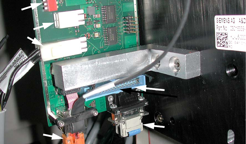
: Pull the three (power supply, CAN bus cable and Hotlink cable) connecting cables for the IC
camera (or five in the case of installation of the FC camera) out of the machine frame.
: Connect the three cables to the camera. More precise information about this can be found in
the appendix of Chapter 2.15 ”Circuit diagrams”, stationary camera for machines of serial num-
ber
≥ B326.
Fig. 2.12 - 2 IC camera with production status
≥
04
2
2
2
2
2
2
2
2
2
2
2
Hotlink cable
(camera bus)
Power supply
Vision control
(Cable from the vision control
unit)
CAN bus cable