00194474-0702_AI_HeadReconfig_X_605_DE+EN.pdf - 第201页
Head Reconfiguration Kits 2 Assemb ly Instructions - SIPLACE X-Series Head Reconfiguration Kits 07/2010 Edition 201 2.12.2.3 From machine serial number B326 and "CO camera, st at. P&P (TYPE33) 55x45 digit."…
2 Assembly Instructions - SIPLACE X-Series Head Reconfiguration Kits Head Reconfiguration Kits
07/2010 Edition
200
2.12.2 Connecting the cameras
2.12.2.1 Up to machine serial number B325 and "CO camera, stat. P&P (TYPE33) 55x45
digit." (item no.: 03016339-) < 04
: Pull the two connecting cables (vision control and hot link cable) for the IC camera (or four in
the case of installation of the FC camera) out of the machine frame.
: Connect both cables to the camera. More precise information can be found in the appendix of
Chapter 2.15 ”Circuit diagrams”, stationary camera for machines of serial numbers ≤ B325 (ig-
nore comments).
Fig. 2.12 - 1 IC camera with production status
≤
02
2
2.12.2.2 Up to machine serial number B325 and "CO camera, stat. P&P (TYPE33) 55x45
digit."(item no.: 03016339-) >= 04
: Pull the three (vision control, CAN bus cable and hotlink cable) connecting cables for the IC
camera (or five in the case of installation of the FC camera) out of the machine frame.
: Connect the three cables to the camera. More precise information about this can be found in
the appendix of Chapter 2.15 ”Circuit diagrams”, stationary camera for machines of serial num-
ber ≤ B325 (observe the comments).
2
2
2
2
2
2
Cables for IC camera
Head Reconfiguration Kits 2 Assembly Instructions - SIPLACE X-Series Head Reconfiguration Kits
07/2010 Edition
201
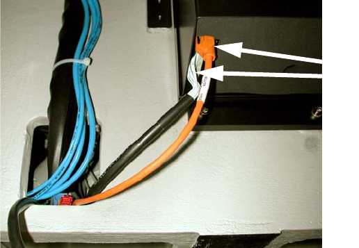
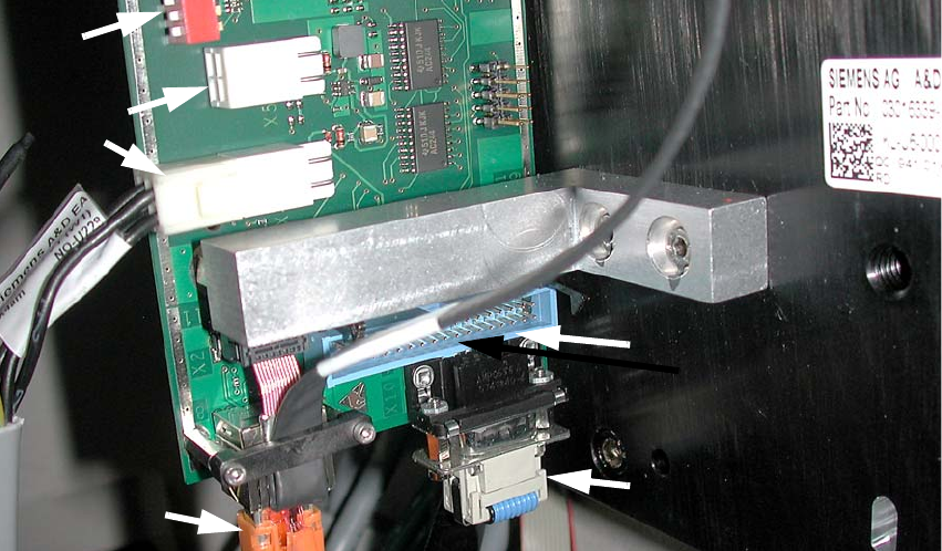
2.12.2.3 From machine serial number B326 and "CO camera, stat. P&P (TYPE33) 55x45
digit."(item no.: 03016339-) >= 04
: Pull the three (power supply, CAN bus cable and Hotlink cable) connecting cables for the IC
camera (or five in the case of installation of the FC camera) out of the machine frame.
: Connect the three cables to the camera. More precise information about this can be found in
the appendix of Chapter 2.15 ”Circuit diagrams”, stationary camera for machines of serial num-
ber
≥ B326.
Fig. 2.12 - 2 IC camera with production status
≥
04
2
2
2
2
2
2
2
2
2
2
2
Hotlink cable
(camera bus)
Power supply
Vision control
(Cable from the vision control
unit)
CAN bus cable
2 Assembly Instructions - SIPLACE X-Series Head Reconfiguration Kits Head Reconfiguration Kits
07/2010 Edition
202
In the case of an IC camera with FS ≥ 04 you must plug this CAN bus cable (03050239-) between
the CAN bus cable of the machine wiring harness and the component trolley docking unit (MTC
drawer frame) X1*5. The X10*m plug is plugged into the camera. 2
2
2
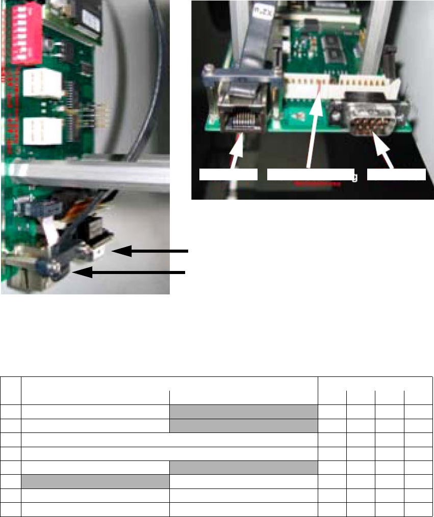
2.12.2.4 Adjustment of the camera-ID (DIP switch configuration FS 04 and larger
2
2
CAN bus
Hotlink
View from below
Vision controller 2 CAN bus 2Hotlink 2
DIP switch Gantry
No.ON OFF 1234
Bootstrap
—
1Reset —
1 Gantry ID 0 Off On Off On
1 Gantry ID 1 Off Off On On
1 Code 1
—
1
With CAN terminating resistor Without CAN terminating resistor
1 CAN speed 1 MBit/s CAN speed = 500 kBit/s
1 IC camera FC camera