00194474-0702_AI_HeadReconfig_X_605_DE+EN.pdf - 第203页
Head Reconfiguration Kits 2 Assemb ly Instructions - SIPLACE X-Series Head Reconfiguration Kits 07/2010 Edition 203 2.12.3 Flip-chip camera : T o install the FC camer a, please read the assemb ly instructions for t he fl…
2 Assembly Instructions - SIPLACE X-Series Head Reconfiguration Kits Head Reconfiguration Kits
07/2010 Edition
202
In the case of an IC camera with FS ≥ 04 you must plug this CAN bus cable (03050239-) between
the CAN bus cable of the machine wiring harness and the component trolley docking unit (MTC
drawer frame) X1*5. The X10*m plug is plugged into the camera. 2
2
2
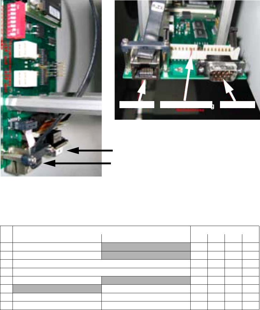
2.12.2.4 Adjustment of the camera-ID (DIP switch configuration FS 04 and larger
2
2
CAN bus
Hotlink
View from below
Vision controller 2 CAN bus 2Hotlink 2
DIP switch Gantry
No.ON OFF 1234
Bootstrap
—
1Reset —
1 Gantry ID 0 Off On Off On
1 Gantry ID 1 Off Off On On
1 Code 1
—
1
With CAN terminating resistor Without CAN terminating resistor
1 CAN speed 1 MBit/s CAN speed = 500 kBit/s
1 IC camera FC camera
Head Reconfiguration Kits 2 Assembly Instructions - SIPLACE X-Series Head Reconfiguration Kits
07/2010 Edition
203
2.12.3 Flip-chip camera
: To install the FC camera, please read the assembly instructions for the flip-chip camera, SI-
PLACE X series (item no.:00194554-).
The FC camera can be fitted and connected up in the same way. 2
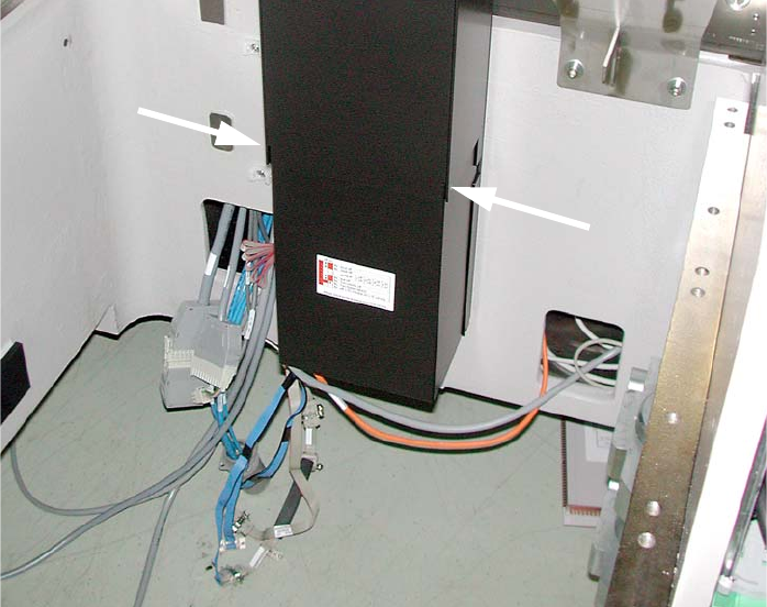
: Place the supporting frame for the camera on the base plate such that it engages below with
the recesses.
: Use the machine spirit level to check that the camera is aligned horizontally.
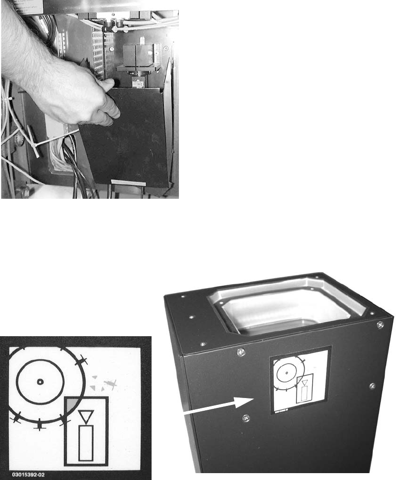
: Attach the "Risk of head crash" warning label to the body of the camera as shown below (if it
is not already attached).
2
2 Assembly Instructions - SIPLACE X-Series Head Reconfiguration Kits Head Reconfiguration Kits
07/2010 Edition
204
: Then carefully place the body of the camera on the supporting frame.
: Screw it firmly onto the supporting frame (3 bolts).
2.12.4 Setting the DIP switches on the vision control unit for the TwinHead
Mixing of different camera types (< FS04 / ≥ FS04) is not recommended and is also not
described in this chapter.
2.12.4.1 Machine serial number >= B326 and IC camera version >= FS04 (FC camera >= FS03)
From B326 the "CO camera, stat. P&P (TYPE33) 55x45 digit." (item no. 03016339-) ≤ 04 is
required. This camera does not require a vision control unit.
2
See Chapter 2.15, ”Circuit diagrams” from machine serial number B326
2
2
2
2
2