00194474-0702_AI_HeadReconfig_X_605_DE+EN.pdf - 第206页
2 Assembly Instructions - SIPLACE X-Series Head Reconfiguration Kits Head Reconfiguration Kits 07/2010 Edition 206 : Changeover the DIP switch on the "Control un it 1, vision stationary" (item no. 00363961-) : …
Head Reconfiguration Kits 2 Assembly Instructions - SIPLACE X-Series Head Reconfiguration Kits
07/2010 Edition
205
2.12.4.2 Machine serial number =< B325 and IC camera, version >= FS04 (FC camera >=
FS03)
: Mount "Control unit 1 Vision stationary" (item no. 00363961-) in the appropriate slot.
The vision control unit for placement area 1 is located in the main distributor (location 4). 2
The vision control unit for placement area 2 is located in the main distributor (location 2). 2
: Unplug the CAN bus cable (X2) on the "Control unit 1 Vision stationary" (item no. 00363961-)
if present.
: Remove the existing TQM module on the vision control unit if present.
2
CAUTION: Faults can subsequently occur on the CAN bus otherwise.
The CAN bus cable must be insulated with an adhesive tape and fixed to a wiring harness to
avoid malfunctions.
2
: Plug the "adapter cable for power cameras" (item no. 03059912-01) between the X4 or X5
"Control unit 1 Vision stationary" (item no. 00363961-) and the black cable.
See Chapter 2.15 ”Circuit diagrams” up to machine serial no. B325 (observe comments). 2
2
SUB 2
MAIN 2
Vision control unit without a CAN bus
and without a TQM module 2

2 Assembly Instructions - SIPLACE X-Series Head Reconfiguration Kits Head Reconfiguration Kits
07/2010 Edition
206
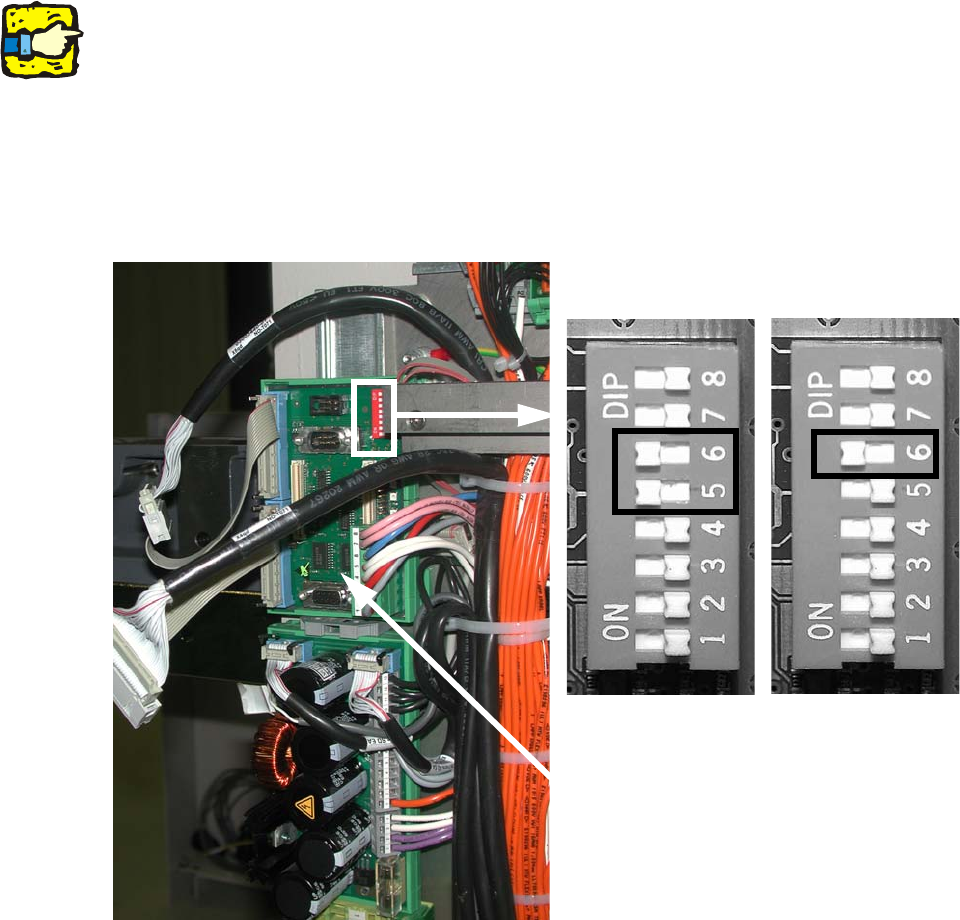
: Changeover the DIP switch on the "Control unit 1, vision stationary" (item no. 00363961-) :
– for a sub-distributor (SD): 5 and 6 to ON, the others to OFF. 2
– for a main distributor (MD): 6 to ON, the others to OFF. 2
2.12.4.3 Machine serial number =< B325 and IC camera version < FS04 (FC camera < FS03)
TQM167 SIPLACE Embedded module" item no. 03003536- to the "Control unit 1 Vision station-
ary" (item no. 00363961-) is required. This TQM module may need to be ordered separately. 2
: Mount "Control unit 1 Vision stationary" (item no. 00363961-) in the appropriate slot.
– The vision control unit for placement area 1 is located in the main distributor (location 4).
– The vision control unit for placement area 2 is located in the main distributor (location 2).
: Plug the TQM module on the board "Control unit 1 Vision stationary" (item no. 00363961-).
2
CAUTION: After power up of the machine, also check the BIOS and application version of the
vision and perform a download, if necessary.
2
2
2
2
2
2
2
2
2
2
2
2
2
2
2
2
2
2
2
Head Reconfiguration Kits 2 Assembly Instructions - SIPLACE X-Series Head Reconfiguration Kits
07/2010 Edition
207
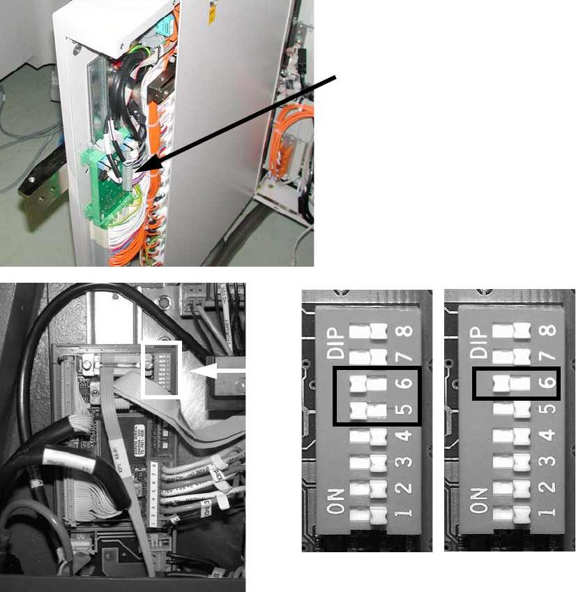
: Attach the CAN bus to X2.
: Attach the black camera cable to the VISION control unit.
: Changeover the DIP switch on the "Control unit 1 Vision stationary" (item no. 00363961-) :
– for a sub-distributor (SD): 5 and 6 to ON, the others to OFF.
– for a main distributor (MD): 6 to ON, the others to OFF.
2
See picture below or Chapter 2.15 ”Circuit diagrams” for machines up to serial number B325 (ig-
nore comments) 2
2
2
Control cable
for the vision control unit
SUB 2
MAIN 2