00194474-0702_AI_HeadReconfig_X_605_DE+EN.pdf - 第209页
Head Reconfiguration Kits 2 Assemb ly Instructions - SIPLACE X-Series Head Reconfiguration Kits 07/2010 Edition 209 2.12.5 Hotlink card connect ions (computer unit) Hotlink card for cameras in P A 1 Hotlink card for came…
2 Assembly Instructions - SIPLACE X-Series Head Reconfiguration Kits Head Reconfiguration Kits
07/2010 Edition
208
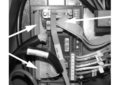
: Check whether the CAN bus connector and the ribbon cable for the camera connection are
plugged in.
CAN bus connector
Camera cable
Head Reconfiguration Kits 2 Assembly Instructions - SIPLACE X-Series Head Reconfiguration Kits
07/2010 Edition
209
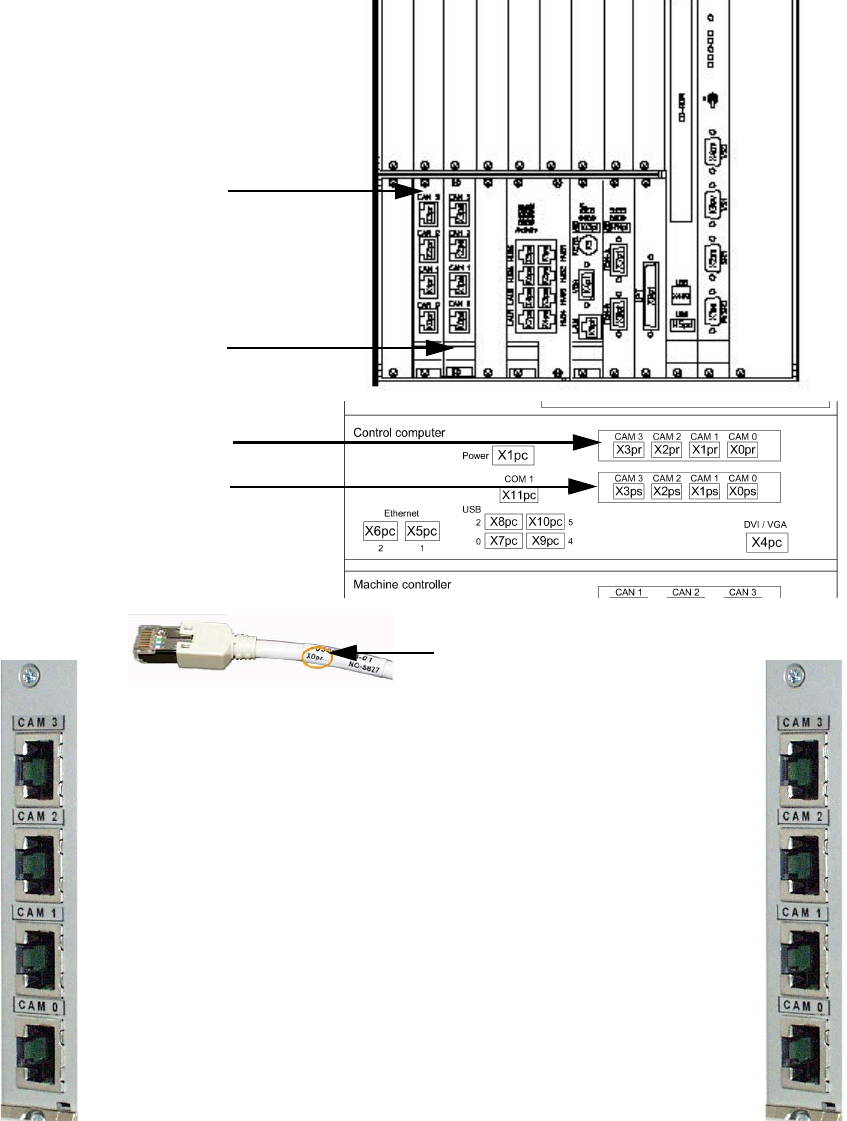
2.12.5 Hotlink card connections (computer unit)
Hotlink card for
cameras in PA 1
Hotlink card for
cameras in PA 2
Hotlink cable labeling
IC / FC camera in PA 1
X3pr
PCB/CO cameras in PA 1
Gantry 1, X0pr
PCB/CO cameras in PA 1
Gantry 4, X1pr
IC camera in PA 1
X2pr
IC / FC camera in PA 2
X3ps
IC camera in PA 2
X2ps
PCB/CO cameras in PA 2
Gantry 3, X1ps
PCB/CO cameras in PA 2
Gantry 2, X1ps
Hotlink card for
cameras in PA 1
Hotlink card for
cameras in PA 2
2 Assembly Instructions - SIPLACE X-Series Head Reconfiguration Kits Head Reconfiguration Kits
07/2010 Edition
210
2
More precise information on this can be found in the appendix in Chapter 2.15 ”Circuit diagrams”.
2
Hotlink cables that are not being used MUST NOT be plugged in.
Do not confuse the hotlink cable with twisted pair cables!!!
2
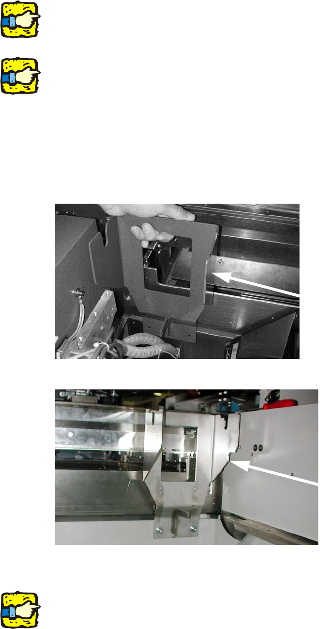
2.12.6 Converting the nozzle changer and the component reject bin
: Insert the fixing for the P&P / TwinHead reject bin and screw it on (fixing screws for holder for
the P&P reject bin DIN912 M6x14 - 8.8, item no.:
0095046-).
2
2
: Remove the sensor for the C&P head reject bin and wire it to the new reject bin for the P&P or
TwinHead.
2
On the subject of the reject bin sensor, also read the assembly instructions for the reject bin sen-
sor, SIPLACE HF series / X series (item no.:00194550-). 2
Locations 1 and 3
Locations 2 and 4