00194474-0702_AI_HeadReconfig_X_605_DE+EN.pdf - 第213页
Head Reconfiguration Kits 2 Assemb ly Instructions - SIPLACE X-Series Head Reconfiguration Kits 07/2010 Edition 213 2 Fig. 2.12 - 5 Mounting position for the nozzle changer ho lder on the left side X-Machine with MA No .…
2 Assembly Instructions - SIPLACE X-Series Head Reconfiguration Kits Head Reconfiguration Kits
07/2010 Edition
212
: Attach the changer with 4 x DIN912 M5x14 - 8.8, (item no. 0306631-) on both holders.
2
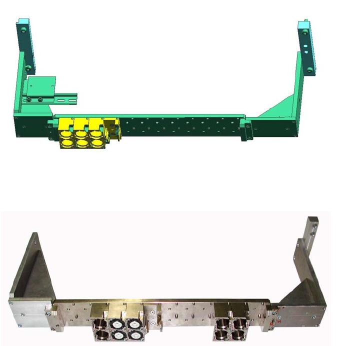
Fig. 2.12 - 3 TH - Nozzlechanger for X-Machine with MTC and MA No. Dxxx
Fig. 2.12 - 4 TH - Nozzlechanger for X-Machine with MTC and MA No. Bxxx
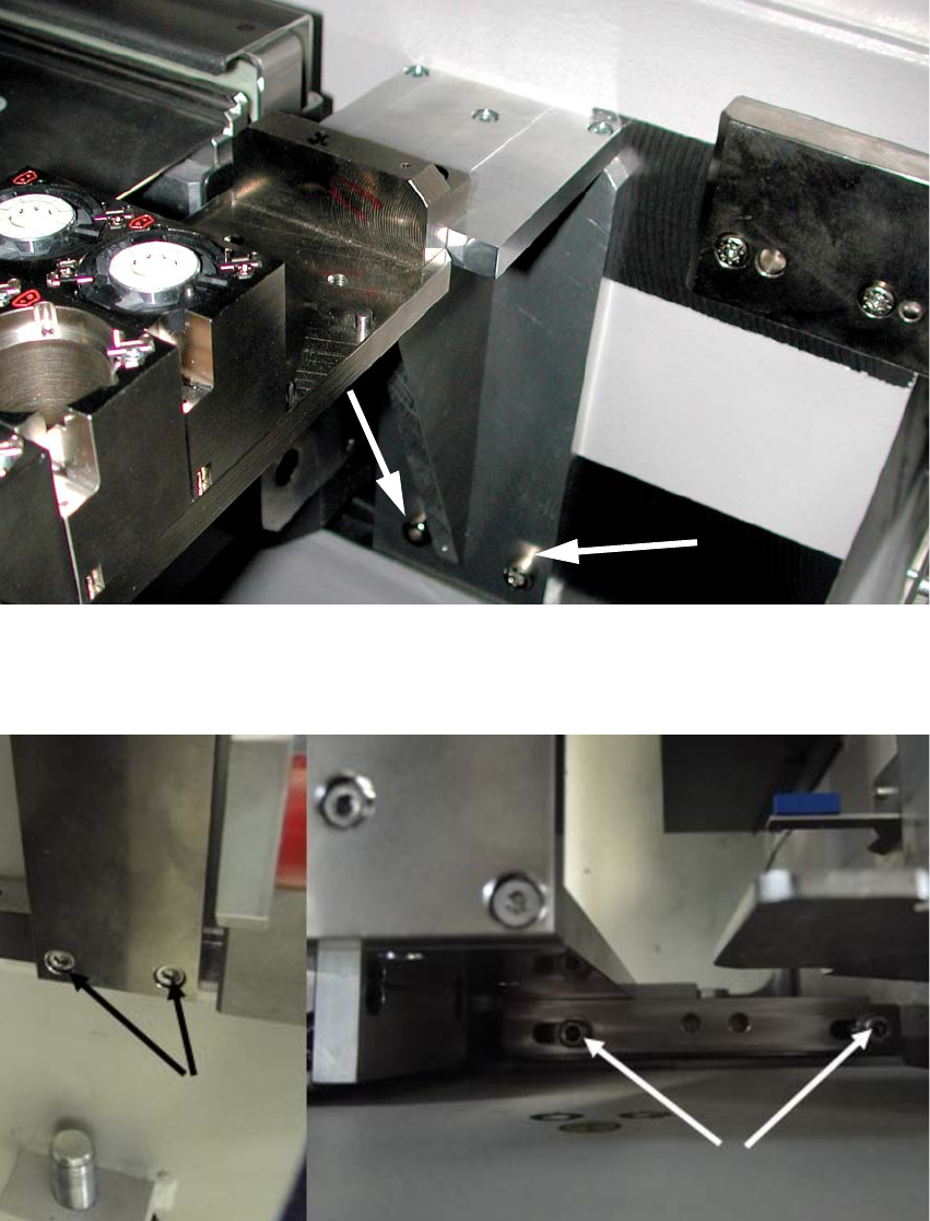
: Attach the nozzle changer incl. holder on the machine frame or the supporting disc of the MTC
drawer frame (on the left with M6x30; on the right with M6x45).
Head Reconfiguration Kits 2 Assembly Instructions - SIPLACE X-Series Head Reconfiguration Kits
07/2010 Edition
213
2
Fig. 2.12 - 5 Mounting position for the nozzle changer holder on the left side X-Machine with MA No. Bxxx
2
2
2
Fig. 2.12 - 6 Mounting position for the nozzle changer holder on the right side X-Machine with MA No. Bxxx
2
2
2 Assembly Instructions - SIPLACE X-Series Head Reconfiguration Kits Head Reconfiguration Kits
07/2010 Edition
214
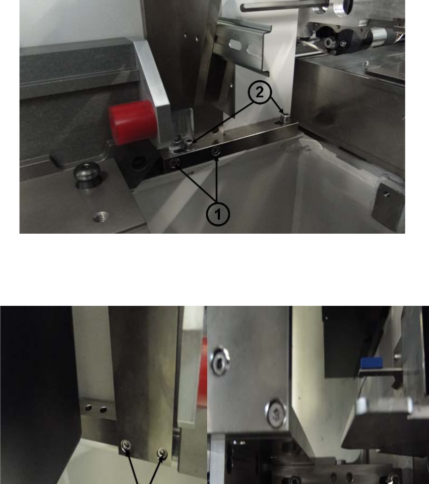
The nozzlechanger holder for Machine with MA No. Dxxx is mounted on the support surface of
the COT docking unit. For that an additional metal bar have to mount on the left side of the nozzle
changer holder. 2
1. Attach the metal bar with two screws on the nozzle changer holder
2. Attach the nozzle changer holder on the machine frame
2
Fig. 2.12 - 7 Mounting position for the nozzle changer holder on the left side X-Machine with MA No. Dxxx
3. Screws to fix the metal bar on the right side of the nozzle changer holder
4. Attach the nozzel changer holder on the support surface of the COT docking unit
2
Fig. 2.12 - 8 Mounting position for the nozzle changer holder on the right side X-Machine with MA No. Dxxx