00194474-0702_AI_HeadReconfig_X_605_DE+EN.pdf - 第216页
2 Assembly Instructions - SIPLACE X-Series Head Reconfiguration Kits Head Reconfiguration Kits 07/2010 Edition 216 : Set all switches to OFF befo re installing the P&P head adapt er board (item no.: 03000902-). 2 : P…
Head Reconfiguration Kits 2 Assembly Instructions - SIPLACE X-Series Head Reconfiguration Kits
07/2010 Edition
215
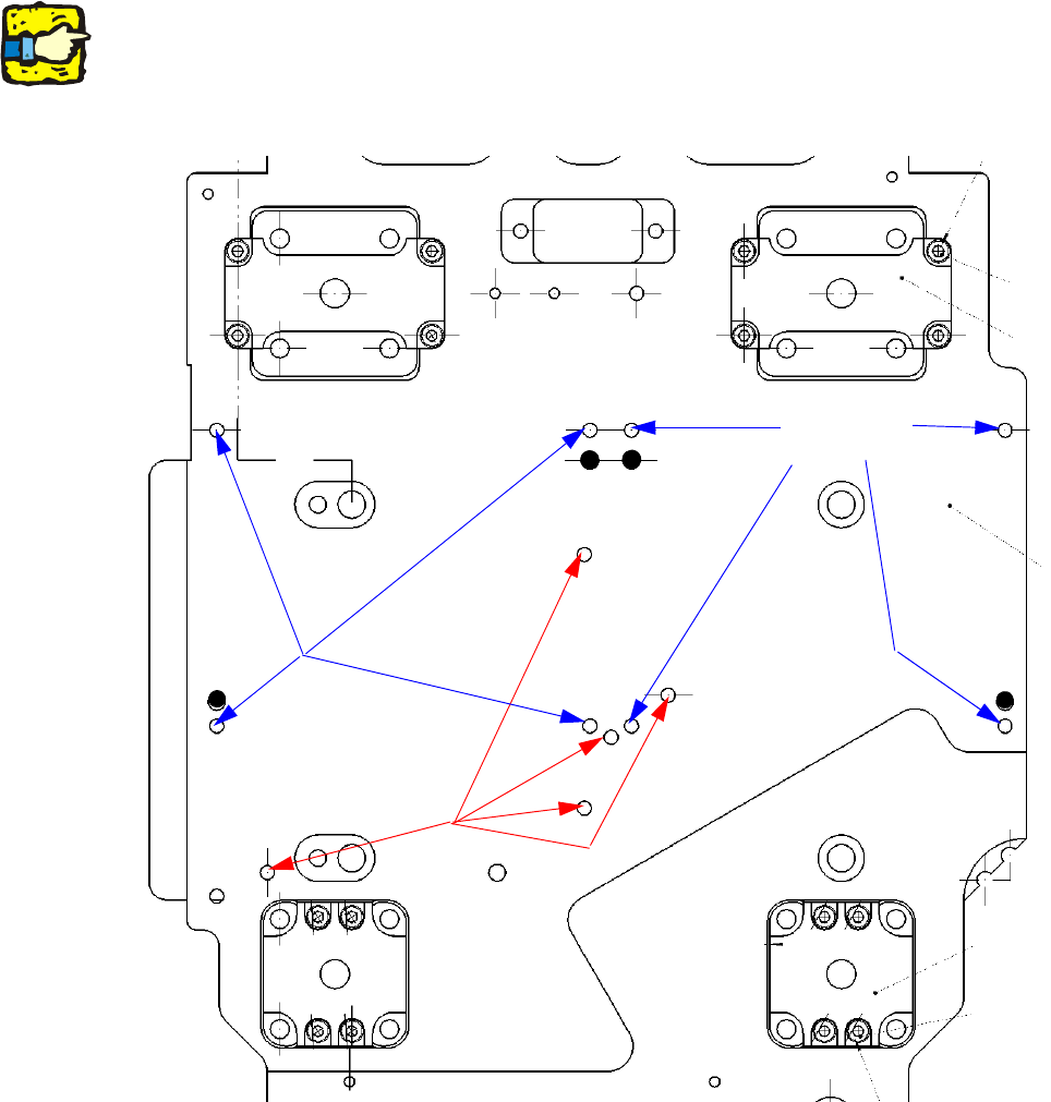
2.12.7 Installing the TwinHead
: Place the TwinHead template on the head fixing plate.
Remove any excess screws and add any necessary screws:
fixing screws: 8x DIN912 M4x14 - 8.8 (item no. 00095021-),
sealing screws: 5x DIN913 M4x6 - ST (item no. 00309422-), secure with gray thread lock paint
(item no. 00318199-)!
Screws in the wrong place could affect the flow of cooling air to the X-axis motor.
2
2
2
Always use the standard tool.
Make sure that the screws are of the right length. The lengths are different for C&P heads and the
TwinHead. If you use the wrong screws, there is a risk of damaging the thread in the head plate.
Tightening torque for the fixing screws: 2.7 Nm. 2
Seal for
head plate
Fixing
for module 2
Fixing
for module 1
2 Assembly Instructions - SIPLACE X-Series Head Reconfiguration Kits Head Reconfiguration Kits
07/2010 Edition
216
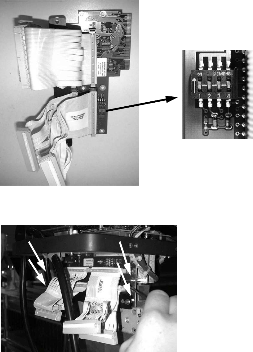
: Set all switches to OFF before installing the P&P head adapter board (item no.: 03000902-).
2
: Plug the head adapter board from below into the head interface board (item no. 03000902-)
and screw in place with the four screws DIN912 M3x6 -A2 (item no. 00201463-).
2
2
Head Reconfiguration Kits 2 Assembly Instructions - SIPLACE X-Series Head Reconfiguration Kits
07/2010 Edition
217
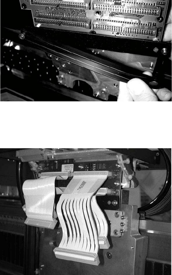
: Fit the strain relief (cable support, P&P head, item no.: 03005195-) to the new board (the push-
button must be on the outside of the gantry).
2
: Plug in the new cables as follows:
the shorter cables on the inner (rear) module, the longer cables on the outer module, the very
short cables at the bottom, the longer cables on top.
2
2
2
2
2
2
2