00194474-0702_AI_HeadReconfig_X_605_DE+EN.pdf - 第217页
Head Reconfiguration Kits 2 Assemb ly Instructions - SIPLACE X-Series Head Reconfiguration Kits 07/2010 Edition 217 : Fit the strain relief (cable su pport, P&P head, item no.: 03005195-) to the ne w board (the push-…
2 Assembly Instructions - SIPLACE X-Series Head Reconfiguration Kits Head Reconfiguration Kits
07/2010 Edition
216
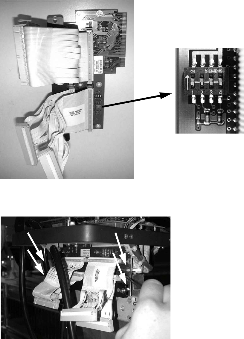
: Set all switches to OFF before installing the P&P head adapter board (item no.: 03000902-).
2
: Plug the head adapter board from below into the head interface board (item no. 03000902-)
and screw in place with the four screws DIN912 M3x6 -A2 (item no. 00201463-).
2
2
Head Reconfiguration Kits 2 Assembly Instructions - SIPLACE X-Series Head Reconfiguration Kits
07/2010 Edition
217
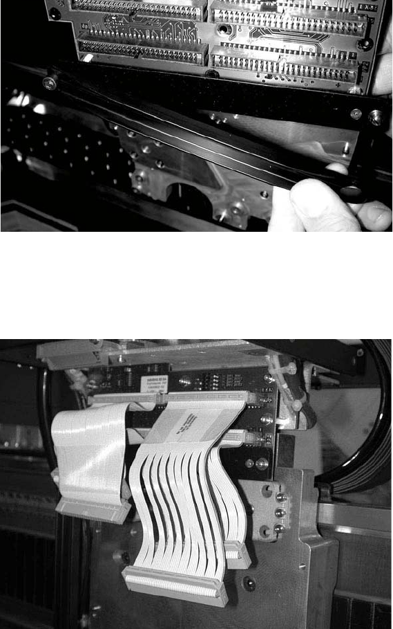
: Fit the strain relief (cable support, P&P head, item no.: 03005195-) to the new board (the push-
button must be on the outside of the gantry).
2
: Plug in the new cables as follows:
the shorter cables on the inner (rear) module, the longer cables on the outer module, the very
short cables at the bottom, the longer cables on top.
2
2
2
2
2
2
2
2 Assembly Instructions - SIPLACE X-Series Head Reconfiguration Kits Head Reconfiguration Kits
07/2010 Edition
218
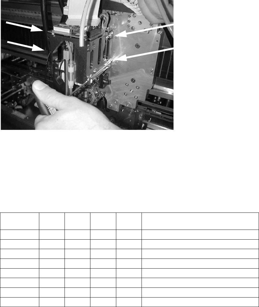
: Start by fitting the inner TwinHead module (module 1) with four screws (because these screws
are more easily accessible).
Make sure that the screws are the right length and that you are using the correct torque:
DIN912 M4x14 - 8.8(item no.: 00095021-), tightening torque: 2.7 Nm.
2
2
: Before attaching the outer module (module 2) to the head, insert the screws into the holes be-
tween the modules.
: Screws on the outer module , turned through 180° around the D axis.
2
: Check the jumper settings on the C500 head interface board.
2
Jumper
Gantry
1
Gantry
2
Gantry
3
Gantry
4
1
0 1 0 1 Gantry ID0
2
0 0 1 1 Gantry ID1
3
0 0 0 0 120 Ohm CAN terminating resistor
4
0 0 0 0 Boot
5
0 0 0 0 Reset
6
0 0 0 0 CAN ID0
7
0 0 0 0 CAN ID1
8
0 0 0 0 Write protect deactivated