00194474-0702_AI_HeadReconfig_X_605_DE+EN.pdf - 第227页
Head Reconfiguration Kits 2 Assemb ly Instructions - SIPLACE X-Series Head Reconfiguration Kits 07/2010 Edition 227 2.13.2 Inst alling and setting the height of the nozzle st ation (description for component trol ley doc…

2 Assembly Instructions - SIPLACE X-Series Head Reconfiguration Kits Head Reconfiguration Kits
07/2010 Edition
226
2.13 Installing the C&P 20 placement head
2
The C&P 20 placement head must be fitted on both gantries on placement areas with two gantries.
It cannot be used together with other placement heads in a placement area. 2
The C&P 20 placement head can only be used in conjunction with the component trolley docking
unit for the X-series and X feeder modules. 2
2.13.1 Installing the nozzle changer for the C&P 20 placement head
: To install the nozzle changer, please read the assembly instructions for the X series nozzle
changer (item no.:00194482-).
2
Risk of a head crash: Always run the placement heads with the appropriate nozzle changer. The
wrong nozzle changer causes a risk of a head crash. 2
2
2
On the subject of the reject bin sensor, also read the
assembly instructions for the reject bin sensor, SIPLACE HF series / X series
(item no.:00194550-). 2
2
Head Reconfiguration Kits 2 Assembly Instructions - SIPLACE X-Series Head Reconfiguration Kits
07/2010 Edition
227
2.13.2 Installing and setting the height of the nozzle station
(description for component trolley docking unit 03015680-06 with
1-wire hub)
: Disconnect the air hose from the component trolley docking unit.
2
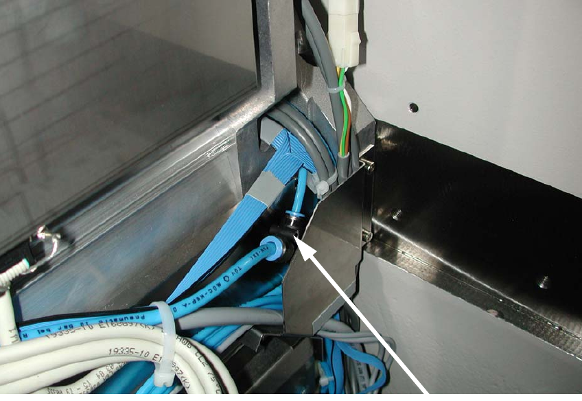
: Connect the T-piece "Plug-in connector QSMT-4" (item no.: 03046434-) with the PUN-CM
4x0.75 40 mm (item no.: 03046289-) to the T-piece and PUN hose from the component trolley
docking unit (see photograph).
2
2
2
2
2
2
2
2
T-piece on the component
2 Assembly Instructions - SIPLACE X-Series Head Reconfiguration Kits Head Reconfiguration Kits
07/2010 Edition
228
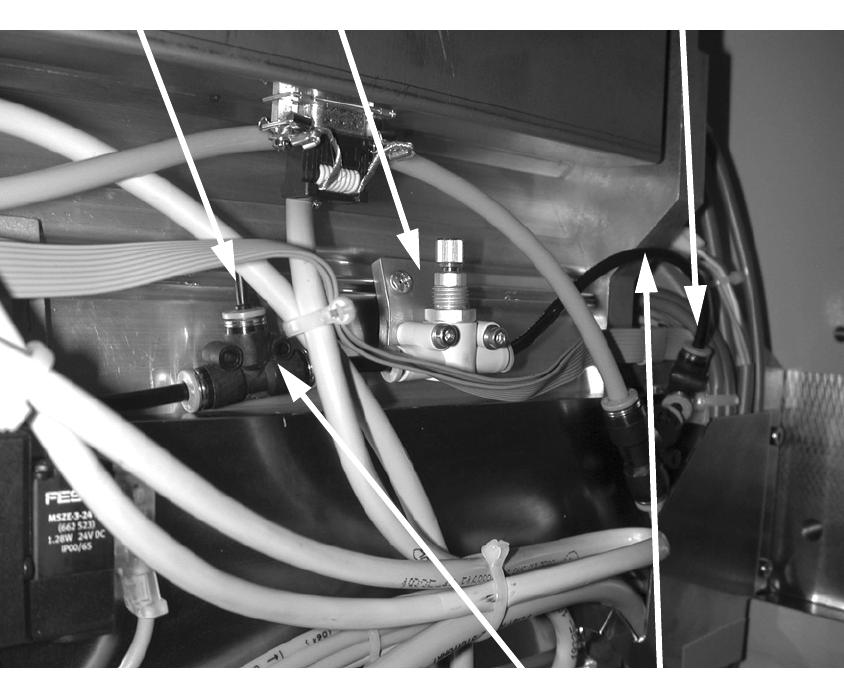
: Use the screws "DIN912 M3x18 -A2-70“ (item no.:03045034-) to attach the "Fine flow restrictor
GRO-QS-4-LF“ (item no.:03045754-) to the "Retaining plate for flow restrictor“ (item
no.:03046270-) and then use the screws "DIN7981 ST3.5x6.5-C-H-A2“ (item no.:03046777-)
to attach the plate to the tape guide channel (see photograph).
: Remove the "Plug QSC-4H" (item no.: 00330249-) for setting the forced air (see photograph).
: Connect the flow control valve to the "PUN-CM 4x0.75 70 mm" hoses (item no.: 03046291-)
using the two T-pieces.
2
2
2
2
2
2
T-piece for plug-in connector QSMT-4
Fine flow restrictor
Blanking plug
Connect flow control valve
using hoses