00194474-0702_AI_HeadReconfig_X_605_DE+EN.pdf - 第230页
2 Assembly Instructions - SIPLACE X-Series Head Reconfiguration Kits Head Reconfiguration Kits 07/2010 Edition 230 Compress ed air setting 2 : Connect a forced air measuring device to the T -piece (plug). Use the fine fl…
Head Reconfiguration Kits 2 Assembly Instructions - SIPLACE X-Series Head Reconfiguration Kits
07/2010 Edition
229
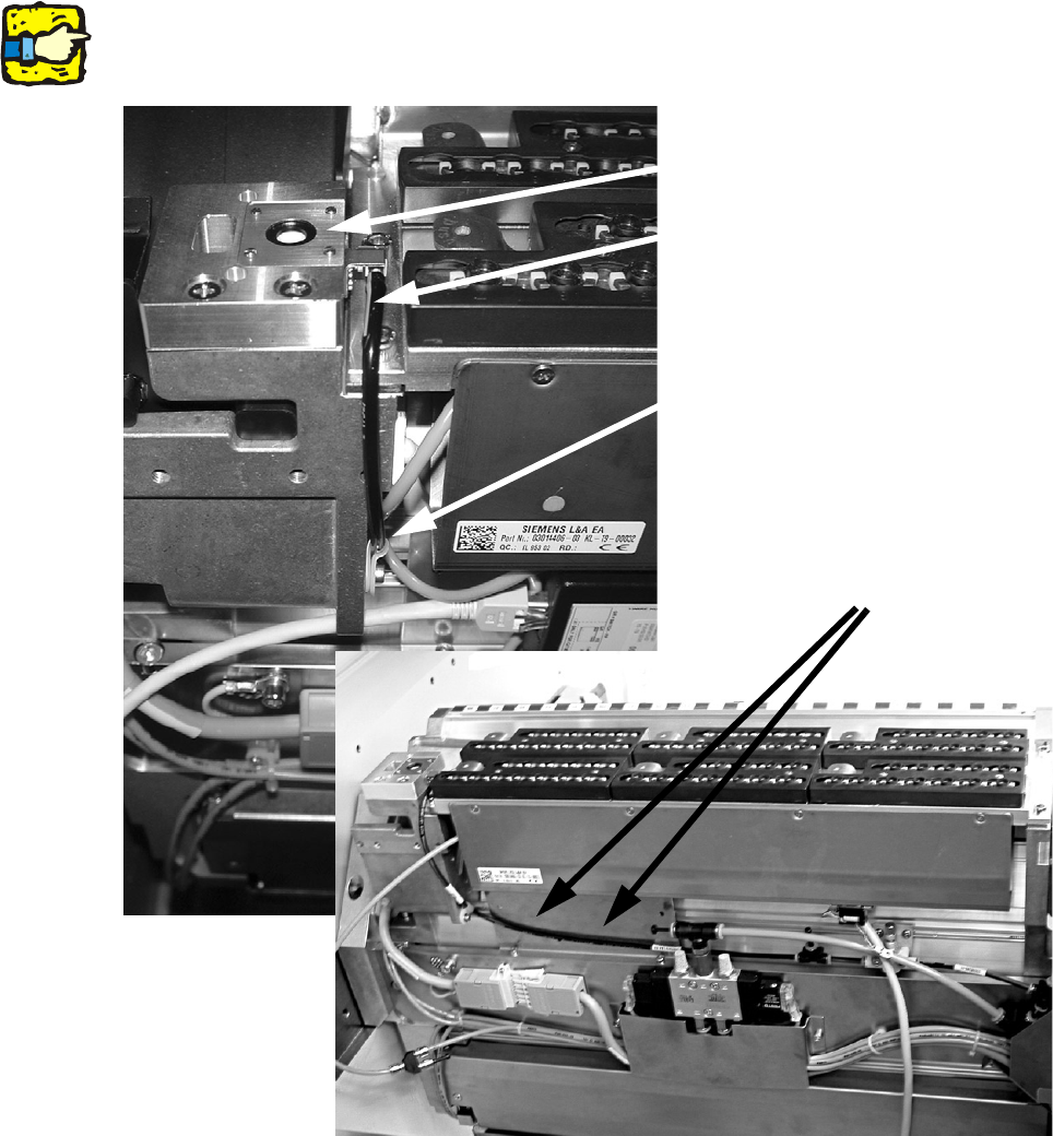
: Fit the nozzle station (item no.: 03045404-) using two screws "DIN7991 M4x20 - 8.8" (item no.:
00333782-).
: Run the long hose "PUN-CM 4x0.75 420 mm" (item no.: 03046432-) as far as the T-piece (see
photograph).
: Secure this hose with a cable clip "Clip Panduit CC S12-S08 D3.1 b 8.2" (item no.
00368063-) and a screw "DIN912 M3x6 - A2-70" (item no.:03045028-).
2
Make sure that the hose is run in front of the retaining plate for the 1-wire hub. 2
2
Nozzle station
Hose "PUN-CM 4x0.75 420 mm"
Cable clip
Hose run
2 Assembly Instructions - SIPLACE X-Series Head Reconfiguration Kits Head Reconfiguration Kits
07/2010 Edition
230
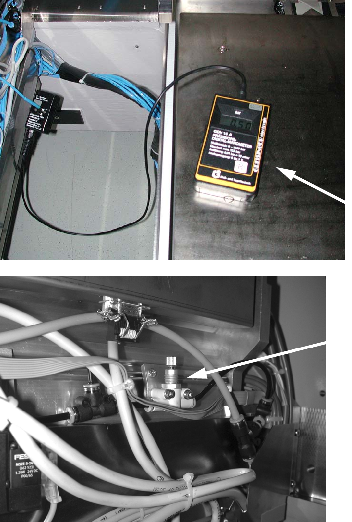
Compressed air setting 2
: Connect a forced air measuring device to the T-piece (plug).
Use the fine flow restrictor to set a pressure of 0.5 bar.
2
2
2
Fine flow
restrictor
Measuring
device:
Head Reconfiguration Kits 2 Assembly Instructions - SIPLACE X-Series Head Reconfiguration Kits
07/2010 Edition
231
2.13.3 Installing and setting the height of the nozzle station (description for the new
component trolley docking unit 03015680-07 with CAN node
(tape cutter control board)
2
The component trolley docking unit must be released according to the installation location (single
portal placement area) and pushed outwards. It is essential to read the respectively valid service
manual in this connection. The components must be attached after completing the work and all
attachment parts (nozzle changer) measured again. 2
2
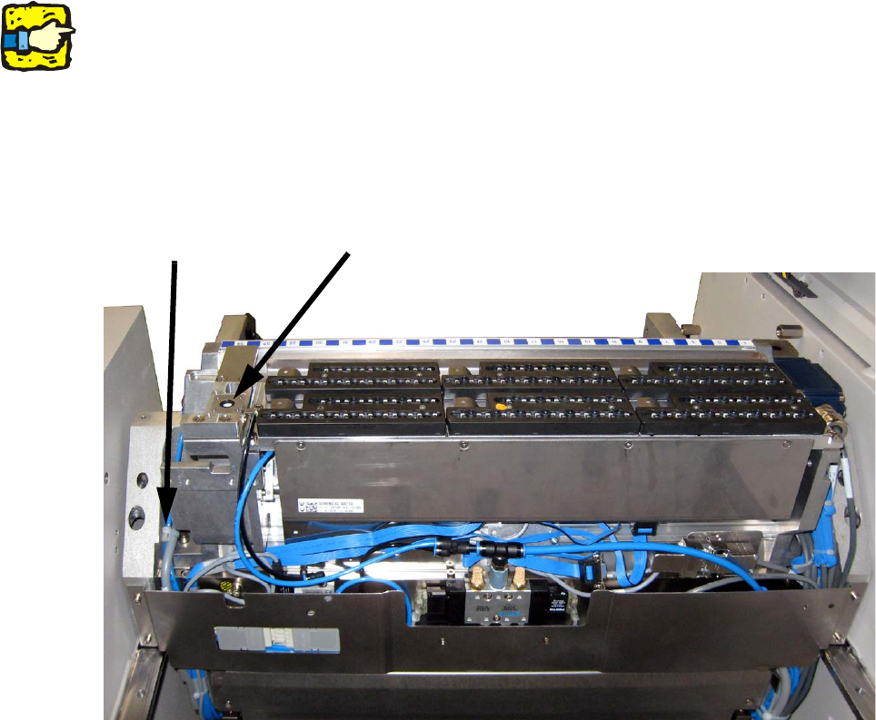
: Remove the cover plate from the component trolley docking unit.
2
2
: If not already done, replace the plugs QSC-6H on docking unit control system solenoid valve
by the "Y plug connection with push-on contact QSY-6H-4" (03055792-).
: Connect the "hose PUN4 125mm" with the Y plug connection and the "valve for nozzle station
complete" (03055785-).
The second opening on the Y plug connection must be connected with the air hose for the noz-
zle changer.
: Connect the hose "hose PUN4 125mm" with the "valve for nozzle station complete" and the
nozzle station.
2
Cable clip
Nozzle station