00194474-0702_AI_HeadReconfig_X_605_DE+EN.pdf - 第233页
Head Reconfiguration Kits 2 Assemb ly Instructions - SIPLACE X-Series Head Reconfiguration Kits 07/2010 Edition 233 : Set the distan ce for all placement heads to 139.0 +/- ±0.2 mm. If the distance is correct, continue b…
2 Assembly Instructions - SIPLACE X-Series Head Reconfiguration Kits Head Reconfiguration Kits
07/2010 Edition
232
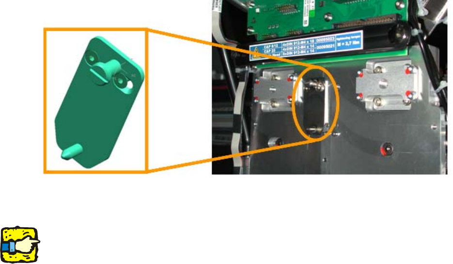
: Connect the already pre-wired "cable docking unit X-series: nozzle station." in the CO trolley
docking unit (03053223-) with the "valve for nozzle station complete"
: Attach the "valve for the nozzle station complete" with two "DIN912-M3 x 16" bolts on the CO
trolley docking unit as shown in the picture above.
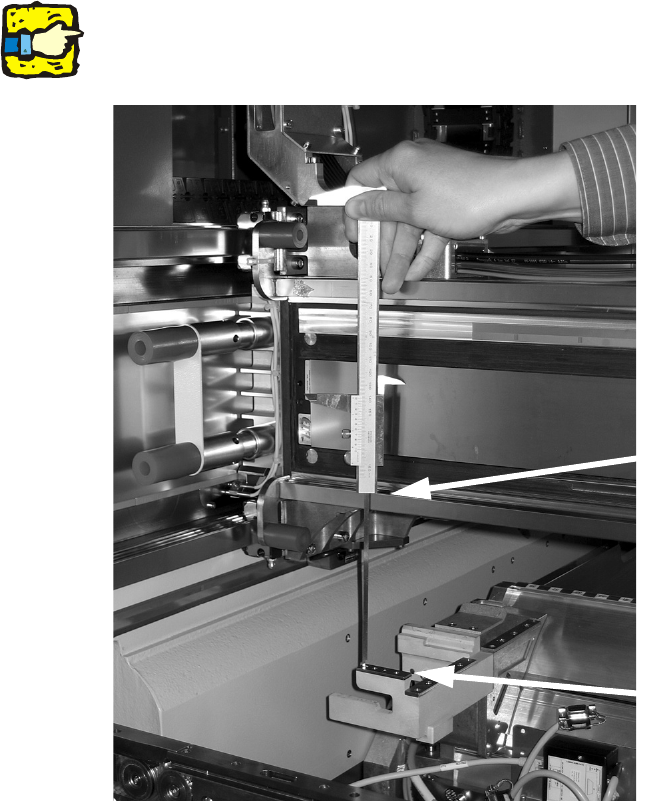
2.13.4 Setting the height of the nozzle ejector
: Push the placement head outwards for the measurement.
2
: Place the caliper gauge on the top edge of the nozzle take-off device and measure the distance
to the top edge of the lower X-axis linear guide.
2
Hold the caliper gauge vertically. 2
2
2
2
Support the bottom edge of the
caliper gauge on the take-off
device
Support the top edge of the caliper
gauge on the linear guide
Head Reconfiguration Kits 2 Assembly Instructions - SIPLACE X-Series Head Reconfiguration Kits
07/2010 Edition
233
: Set the distance for all placement heads to 139.0 +/- ±0.2 mm.
If the distance is correct, continue by installing the nozzle changer in the placement machine.
2
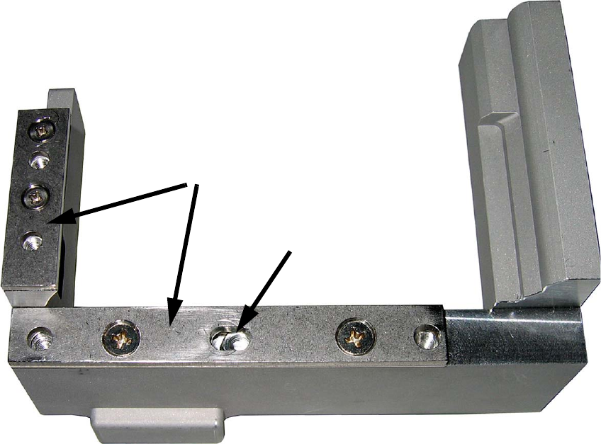
: If the distance is too large, place adjusting plates beneath:
Adjusting plates for nozzle reject device (item no.: 03039514-),
screws DIN7991 M4x20 - 8.8 (item no.: 00333782-).
2
2
2
2
2
2
2
2
Slot
Adjusting plates
2 Assembly Instructions - SIPLACE X-Series Head Reconfiguration Kits Head Reconfiguration Kits
07/2010 Edition
234
2.13.5 Installing the placement head
1.Preparation of the head plate 2
In order to facilitate the replacement and mounting of heads, changes have been made to the
"C&P20A placement head / without camera" [03058420-03] and the "CPP placement head / with-
out camera" [03053528-xx] (Multistar). 2
A retrofitting kit is also offered to allow the retaining plate on C&P20A and CPP placement heads
also to be used on machines that are not yet fitted with the mounting aid. 2
03073841-01 "FHE retrofitting kit for X-Series" 2
The reconfiguration kit contains the retroffiting kit (03073841-01 "FHE retroffiting kit for X-Series").2
2
Fig. 2.13 - 1 Mounting position for the FHE mounting aid
: Attach the FHE mounting aid with the two screws
2
CAUTION:
A placement head that is only attached to the gantry using the FHE lug hangs around 3 mm lower
than a head that has been screwed on. You should therefore only attach the placement head in
positions where there is sufficient clearance underneath. 2
Do not move the gantry as long as the head is not secured! 2
2.Preparation of the head plate 2
: Place the DLM head template on the head fixing plate.
Remove any excess screws and add any necessary screws:
fixing screws: 4x DIN912 M4x14 - 8.8 (item no. 00095021-),
sealing screws: 9x DIN913 M4x6 - ST (item no. 00309422-), secure with gray thread lock paint
(item no. 00318199-)!
Screws in the wrong place could affect the flow of cooling air to the X-axis motor.