00194474-0702_AI_HeadReconfig_X_605_DE+EN.pdf - 第238页
2 Assembly Instructions - SIPLACE X-Series Head Reconfiguration Kits Head Reconfiguration Kits 07/2010 Edition 238 2 : Connect the plugs and att ach the clip. 2 2 : Check the jumper settings on the C500 head interface bo…
Head Reconfiguration Kits 2 Assembly Instructions - SIPLACE X-Series Head Reconfiguration Kits
07/2010 Edition
237
possible damage. 2
2
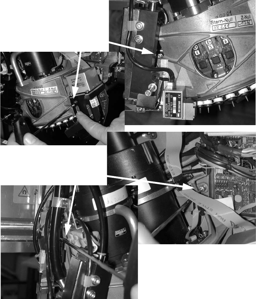
: Position the placement head and screw it firmly in place (4 screws).
Make sure that the screws are the right length and that you are using the correct torque:
DIN912 M4x14 - 8.8 (item no.: 00095021-), tightening torque: 2.7 Nm.
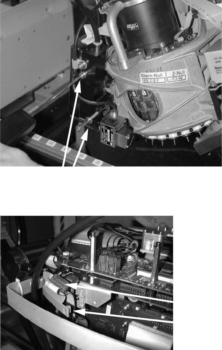
: Tighten the two screws on the pressure control valve.
Screws
Screws
2 Assembly Instructions - SIPLACE X-Series Head Reconfiguration Kits Head Reconfiguration Kits
07/2010 Edition
238
2
: Connect the plugs and attach the clip.
2
2
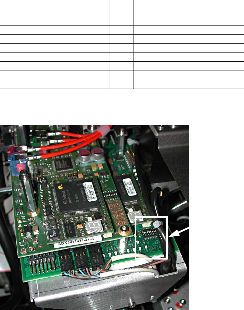
: Check the jumper settings on the C500 head interface board.
Tighten the screw
Attach the clip
Plug in the connec-
Head Reconfiguration Kits 2 Assembly Instructions - SIPLACE X-Series Head Reconfiguration Kits
07/2010 Edition
239
2
: If problems occur with the CAN bus, measure the resistance between pin 7 (CAN High) and
pin 2 (CAN Low). It should be 60 Ohm.
2
2
Jumper
Gantry
1
Gantry
2
Gantry
3
Gantry
4
1
0 1 0 1 Gantry ID0
2
0 0 1 1 Gantry ID1
3
1 1 1 1 120 Ohm CAN terminating resistor
4
0 0 0 0 Boot
5
0 0 0 0 Reset
6
0 0 0 0 CAN ID0
7
0 0 0 0 CAN ID1
8
0 0 0 0 Write protect deactivated
Jumper
position