00194474-0702_AI_HeadReconfig_X_605_DE+EN.pdf - 第244页
2 Assembly Instructions - SIPLACE X-Series Head Reconfiguration Kits Head Reconfiguration Kits 07/2010 Edition 244 2.13.8 Hotlink card conn ections (computer unit) Hotlink card for cameras in P A 1 Hotlink card for camer…
Head Reconfiguration Kits 2 Assembly Instructions - SIPLACE X-Series Head Reconfiguration Kits
07/2010 Edition
243
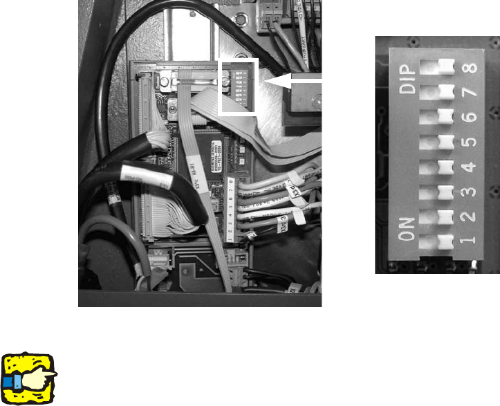
2.13.7 Setting the DIP switches on the vision control unit
The vision control unit should generally be removed for configuration of the C&P 20 head in a
placement area. This is only needed for configuration with a TwinHead. TwinHead and C&P 20 is
not allowed in a placement area. 2
: The associated DIP switches on the vision control unit should be set to OFF according to the
installation location of the C&P placement heads:
– Placement area 1: all MD-DIP switches at OFF.
– Placement area 2: all SD-DIP switches at OFF.
The vision control unit for placement area 1 is located in the main distributor (location 4). 2
The vision control unit for placement area 2 is located in the main distributor (location 2). 2
2
2
2
If there is no TwinHead installed in the same placement area, you can remove the corresponding
vision controller in the sub or main distributor. C&P heads do not require a vision controller. 2
OFF
OFF
OFF
OFF
OFF
OFF
OFF
OFF
2 Assembly Instructions - SIPLACE X-Series Head Reconfiguration Kits Head Reconfiguration Kits
07/2010 Edition
244
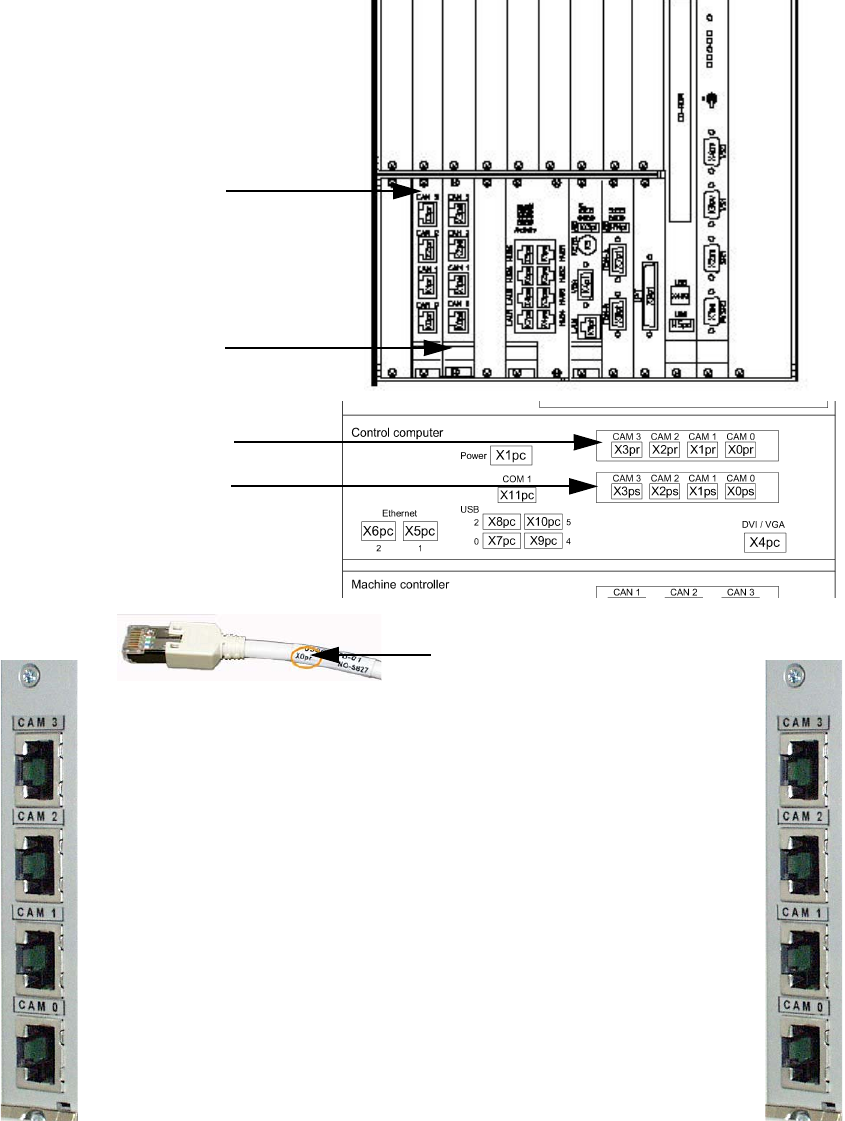
2.13.8 Hotlink card connections (computer unit)
Hotlink card for
cameras in PA 1
Hotlink card for
cameras in PA 2
IC / FC camera in PA 1
X3pr
PCB/CO cameras in PA 1
Gantry 1, X0pr
PCB/CO cameras in PA 1
Gantry 4, X1pr
IC camera in PA 1
X2pr
IC / FC camera in PA 2
X3ps
IC camera in PA 2
X2ps
PCB/CO cameras in PA 2
Gantry 3, X1ps
PCB/CO cameras in PA 2
Gantry 2, X1ps
Hotlink cable labeling
Hotlink card for
cameras in PA 1
Hotlink card for
cameras in PA 2

Head Reconfiguration Kits 2 Assembly Instructions - SIPLACE X-Series Head Reconfiguration Kits
07/2010 Edition
245
2
2
2
The Hotlink cable of the IC and FC camera – for the placement area, in which a C&P 20 head is
located – must be unplugged!
Hotlink cables that are not being used must not be plugged in.
Do not confuse the hotlink cable with twisted pair cables!!! 2
2.13.9 Replacing the servo cards
: Use the machine key to open the door of the servo unit.
: Insert the servo cards in accordance with your machine configuration. See axis unit attachment
A363 or A364.