00194474-0702_AI_HeadReconfig_X_605_DE+EN.pdf - 第75页
Head Reconfiguration Kits 1 Montageanleitung H ead Reconfiguration Kits SIPLACE X-Serie Ausgabe 07/2010 75 : Kontrollieren Sie, ob der CAN-Bus-S tecker un d die Flachband-Kabel des Kamera-Anschlus- ses angesteckt sind. C…
1 Montageanleitung Head Reconfiguration Kits SIPLACE X-Serie Head Reconfiguration Kits
Ausgabe 07/2010
74
: Schließen Sie CAN Bus an X2 an.
: Schließen Sie das schwarze Kamerakabel an die VISION Control Unit an.
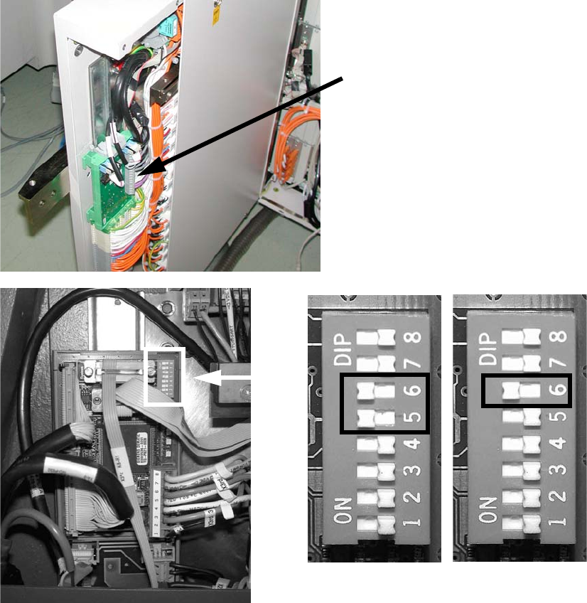
: Stellen Sie an der "Controll-Unit 1 Vision stationär" (Art.Nr. 00363961-) die DIP-Schalter um:
– beim Sub-Distributor (SD): 5 und 6 auf ON, die anderen auf OFF.
– beim Main-Distributor (MD): 6 auf ON, die anderen auf OFF.
1
Siehe Bild unten bzw. Kapitel 1.15 ”Stromlaufpläne” bis Maschinen Serien Nummer B325 (Kom-
mentare ignorieren) 1
1
1
Steuerkabel
Vision Control Unit
SUB 1
MAIN 1
Head Reconfiguration Kits 1 Montageanleitung Head Reconfiguration Kits SIPLACE X-Serie
Ausgabe 07/2010
75
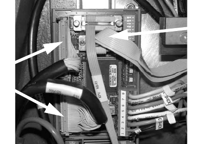
: Kontrollieren Sie, ob der CAN-Bus-Stecker und die Flachband-Kabel des Kamera-Anschlus-
ses angesteckt sind.
CAN-Bus Stecker
Kamera-Kabel
1 Montageanleitung Head Reconfiguration Kits SIPLACE X-Serie Head Reconfiguration Kits
Ausgabe 07/2010
76
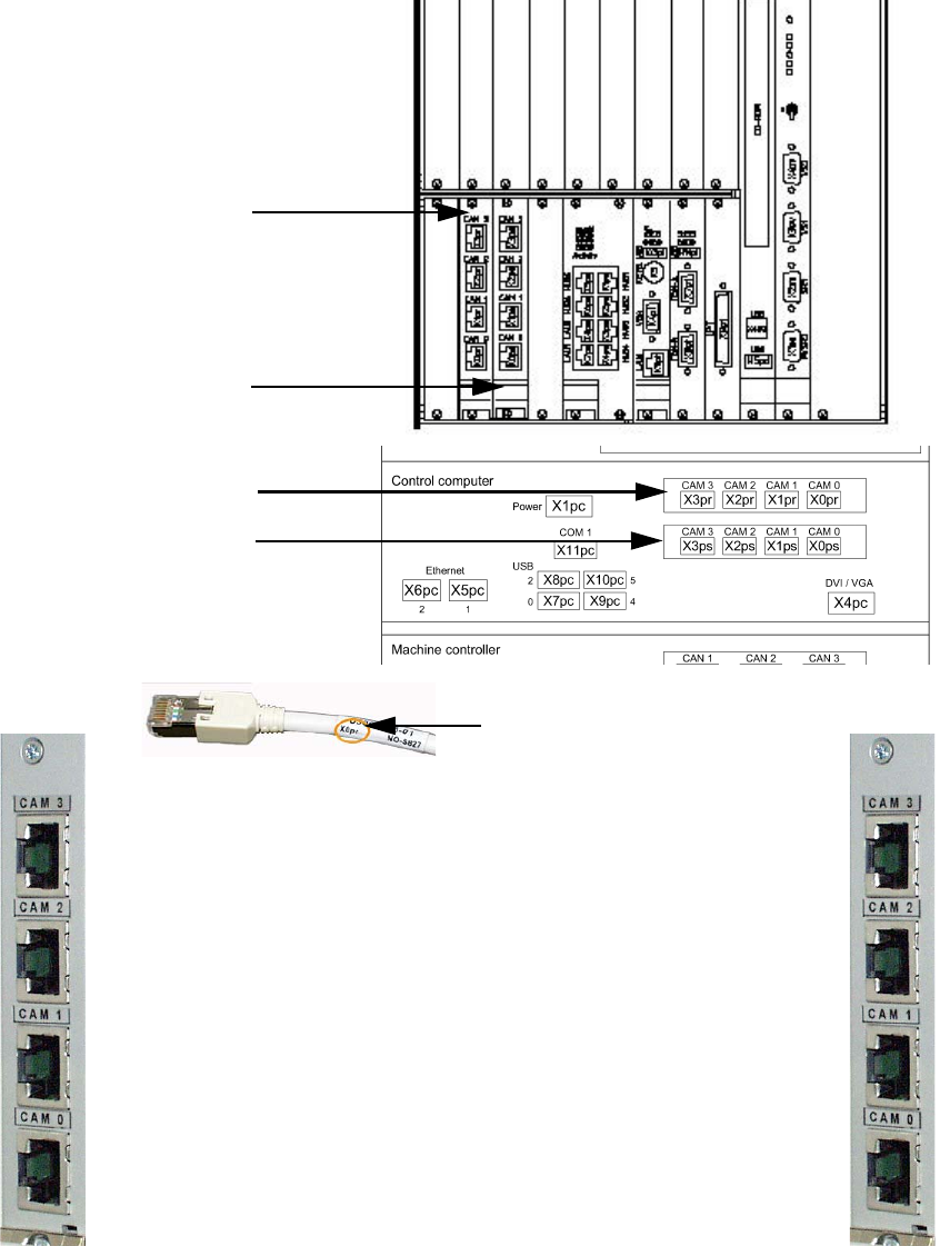
1.12.5 Anschlüsse Hotlink-Karte (Computer Unit)
Hotlink-Karte für
Kameras im BB 1
Hotlink-Karte für
Kameras im BB 2
Beschriftung Hotlink-Kabel
IC / FC Kamera im BB 1
X3pr
LP/BE Kameras im BB 1
Portal 1, X0pr
LP/BE Kameras im BB 1
Portal 4, X1pr
IC Kamera im BB 1
X2pr
IC / FC Kamera im BB 2
X3ps
IC Kamera im BB 2
X2ps
LP/BE Kameras im BB 2
Portal 3, X1ps
LP/BE Kameras im BB 2
Portal 2, X0ps
Hotlink-Karte für
Kameras im BB 1
Hotlink-Karte für
Kameras im BB 2