00195166-0402_SM_D4_EN.pdf - 第100页
Service Work Component Handling Cutter 100 Serv ice Manual SIPLACE D4 See also: J 4.3.2.7 Replacing the Stationary Blad e and Movable Blade incl. Spa cers [ J 95] J Tightening Torques for Cutter Screws [ J 87] J 6.4.…
Service Work
Cutter Component Handling
Service Manual SIPLACE D4
99
X Using the feeler gauge, check the gap between tape deflector and movable blade, over the entire
length and width of the blade:
The 0.05 mm feeler gauge should fit through the gap.
The 0.25 mm feeler gauge should not fit through the gap.
If the gap is not correct, check:
X Whether the wrong holddowns has been installed (with function status < 03).
The holddowns are those designed for cutters with function status -04 (= with tape deflector).
X Whether the blades, tape deflector etc. were cleaned before installation
If the gap is correct:
X Carefully fold the cover plate (with cover plate holders installed) back over the tape deflector.
X Reinstall the previously removed deflector
holder (= with tape deflector) and initially
tighten the 4 hexagon socket head screws (9)
hand-tight.
X Push the spacers (with inserted adjustment
plate) towards the movable blade - up to the
stop but not until they exert pressure against it,
otherwise it would no longer be possible to
remove the adjustment plates.
The maximum permissible gap is 1.0 mm.
X In this position, tighten all 4 screws on the tape
deflector holders crosswise.
Tighten the screws to the correct torque.
X Remove the two shim rings.
X Insert the new stationary blade in the correct
position ((see diagram) and screw tight (2
screws).
Tighten the screws to the correct torque.

Service Work
Component Handling Cutter
100 Service Manual SIPLACE D4
See also:
J
4.3.2.7 Replacing the Stationary Blade and Movable Blade incl. Spacers [
J
95]
J
Tightening Torques for Cutter Screws [
J
87]
J
6.4.3 Check the gap between the empty-tape baffle, inside and the leading edge of the tape deflector.
[
J
241]
J
4.3.2.14 Final Steps [
J
114]
X Make certain that the edges are parallel, then
screw the cover plate holder to the cutter (two
M4 screws each (7, 9)):
-> Do not pinch or put strain on the cables.
X Install the cover plate on the stationary blade
(4 M4 screws (12, 13)).
X Remove the parallel clamps from the cutter or
dismantle the cutter from the mounting plate.
X Fit the cutter back into the machine. (See sec-
tion (4.3.2.5 Exchanging the Pneumatic Cutter
J
87 ) .)
X Fit the empty-tape duct assembly and check
the gap between the empty-tape baffle, inside
and the leading edge of the tape deflector.
X Perform the appropriate “Final Steps”.
Service Work
Cutter Component Handling
Service Manual SIPLACE D4
101
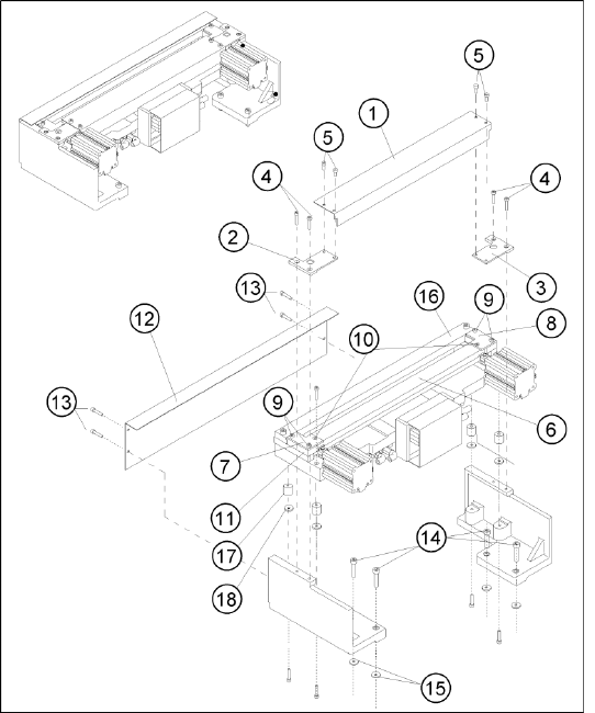
4.3.2.8 Replacing the Articulated Joint on the Short-Stroke Cylinder [00348579-xx]
Removing the articulated joint and short-stroke cylinder
X Remove the cutter from the machine. (See section (4.3.2.5 Exchanging the Pneumatic Cutter
J
87
) .)
X Remove the deflector plate from the cutter.
X Loosen the screws holding the moveable blade.
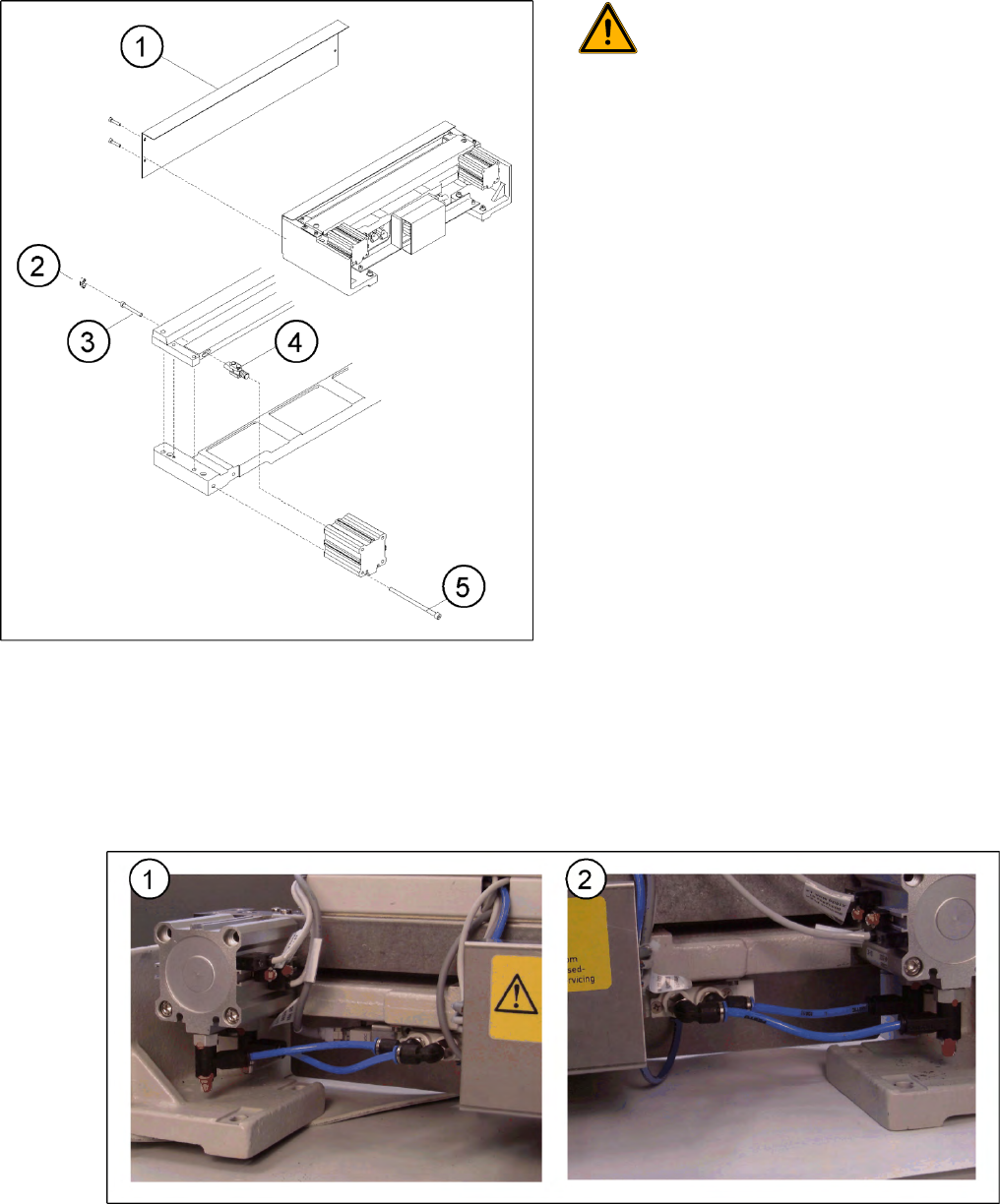
4-34: Compressed air connections, left (1) and right (2)
X Loosen the compressed air connections (1, 2) on the short-stroke cylinder.
X In addition, mark the allocation of the proximity switches to the short-stroke cylinder (position front/
back).
4-33: Replacing the articulated joint on the short-stroke cylinder
WARNING: Risk of injury!
Wear appropriately thick protective
gloves!
There is a high risk of injury from the
blades and the tape deflector.
Never reach into the cutter from below
or into the empty-tape duct from above.
Legend
1. Deflector plate
2. Cover
3. Screws to fasten short-stroke cylinder
4. Articulated joint
5. Screws to fasten the moveable blade