00195166-0402_SM_D4_EN.pdf - 第110页
Service Work Component Handling Cutter 110 Serv ice Manual SIPLACE D4 4.3.2.1 1 Exc hanging the Inductive Proximity Switch Removing the Proximity Switch X The cutter rema ins inst alled in the machine. X Turn the m achin…
Service Work
Cutter Component Handling
Service Manual SIPLACE D4
109
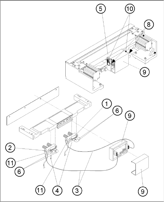
If the cable of the solenoid valve is faulty:
X Carefully undo the relevant cable ties (left or right) on the outside of the control board box(10).
-> Do not damage the cables in this process.
X Remove the cover from the control board (9).
X Unplug the press-fit connection for the "control board for tape cutter - valve" cable of the appropriate
solenoid valve at the control board.
X Unplug the press-fit connection for the "control board for tape cutter - valve" cable at the appropriate
solenoid valve.
X Remove the cover from the cable duct (5).
X Remove the cable and run the new "control board for tape cutter - valve" cable.
Push the excess lengths of cable into the cable duct.
X Reconnect the press-fit connections at the correct points on the board and solenoid valve.
X Refit the cover on the control board (9).
X Install the cover on the cable duct (5).
X Use a cable tie to fasten the cables running to LH and/or RH side of the cable duct to the fixing
pedestal (on control board box).
Make sure the cables/press-fit connections are not subject to strain (8).
X Perform the "Final Steps".
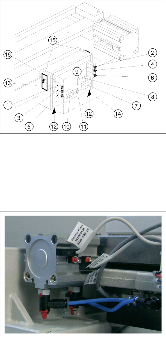
If the solenoid valve is faulty:
X Undo the 2 compressed air connections on the one-way restrictors at the faulty solenoid valve
(1, 2, 6).
X Unplug the press-fit connection for the "control board for tape cutter - valve" cable at the defective
solenoid valve (11).
X Undo the screws fastening the faulty solenoid valve (2 M3 screws (4)) and remove the solenoid
valve.
X Fit the new solenoid valve in the correct position, as shown in the diagram above. Make the plug-
and-socket connection at the solenoid valve:
-> Tighten the screws to the correct torque.
-> The strain on the cable must be relieved (8).
X Mount the short-stroke cylinder compressed air connections to the one-way restrictors on the
solenoid valve with the correct allocation (6,7,8).
X Perform the "Final Steps".
See also:
J
4.3.2.14 Final Steps [
J
114]
J
Tightening Torques for Cutter Screws [
J
87]
Service Work
Component Handling Cutter
110 Service Manual SIPLACE D4
4.3.2.11 Exchanging the Inductive Proximity Switch
Removing the Proximity Switch
X The cutter remains installed in the machine.
X Turn the machine and then the flow of
compressed air ON.
X Disconnect the movable changeover table
from the machine and move it out of the
machine.
X Turn the machine OFF,
X Remove the cover from the control board (14).
X Carefully undo the relevant cable ties (left or
right) on the outside of the control board box
(10).
-> Do not damage the cables in this process.
X Using a fine-tip permanent marker, precisely
mark on the short-stroke cylinder the specified
position of the proximity switch that is to be
exchanged.
X Unplug the press-fit connection for the
defective proximity switch from the control
board (for allocation see diagram). If you
loosen more than one of the press-fit
connections simultaneously, mark the
allocation.
X Remove the cover from the cable duct.
X Undo the screw fastening the proximity switch
to the short-stroke cylinder (1 screw: see
picture) and remove the proximity switch
including the cable.
Service Work
Cutter Component Handling
Service Manual SIPLACE D4
111
Installing the Proximity Switch
See also:
J
Tightening Torques for Cutter Screws [
J
87]
J
4.3.2.14 Final Steps [
J
114]
X Install the new proximity switch precisely in the
position you marked on the short-stroke
cylinder with the permanent marker.
Tighten the screws to the correct torque.
X Run the cable in the cable duct and establish
the press-fit connection to the control board
with correct allocation to the proximity switch
left/right and front/back (for allocation see
diagram above).
Push the excess lengths of cable into the
cable duct.
X Use a cable tie to fasten the cables running to
the cable duct to the fixing pedestal on the
control board box.
Make sure the cables/press-fit connections
are not subject to strain (8).
X Refit the cover (9) on the control board.
X Install the cover on the cable duct (5).
X Perform the "Final Steps" including the
substep "Load the SITEST program and
initiate the cutting strokes".